-
Squidwrench Electronics Workshop: Session 5
Topics for today’s Squidwrench Electronics Workshop: Session 5 in a continuing series.
Having discussed transistors as current-controlled current sources, we can now
select one as a victimuse one as a switch, then add capacitors to learn about exponential charging, and introduce the oscilloscope as a vital tool.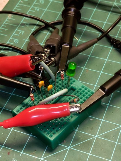
NPN Switch – protoboard So, we proceed:
Transistors as switches
Review graphical parameters
- saturation voltage for high Ic
- cutoff voltage for near-zero Ic
- resistive load line: VR = Vcc – Vc
- power dissipation hyperbola (at all Vc)
- secondary breakdown limit (at higher Vc)
Something like this, only drawn much larger and with actual numbers:

Transistor characteristics – saturation and cutoff – load line Reminder of linear vs. log scales converting hyperbolas into straight lines.
NPN transistor as “to ground” switch
- where to measure device voltages?
- passing mention of flyback diodes
- IB needed for saturation?
- Darlington transistors: beta multiplier, VBE adder
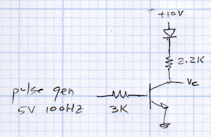
For example:
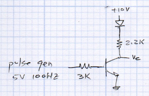
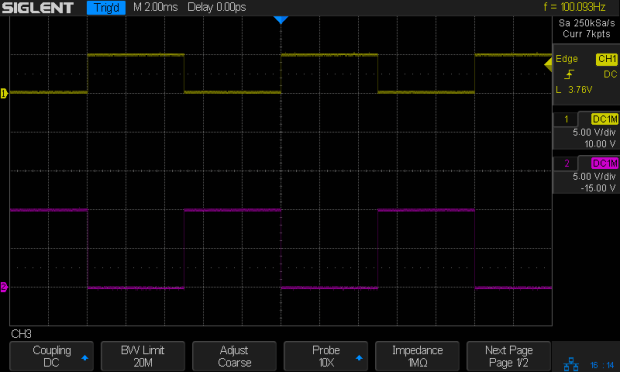
NPN switch – LED Without the LED, you get nice square waves:
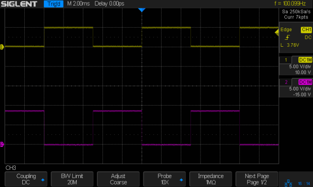
NPN – 100 Hz – 2.2k – no cap – Vc An ancient green LED reduces Vc by a little over a volt:
NPN – 100 Hz – 2.2k green LED – no cap – Vc Discuss PNP transistor as “from supply” switch
- why VCC must not exceed controller VDD
- kill microcontroller and logic gates
Wire up pulse gen to transistor
- function generator for base drive voltage
- collector resistor (then LED) as output
- how do you know what it’s doing?
- add oscilloscope to show voltages
- explanation of scope functions!
Capacitor as charge-storage devices
Useful ideas and equations
- C = Q/V
- so C = ΔQ/ΔV
- therefore i = C * Δv/Δt
- energy = 1/2 * C * V²
Charging capacitor from a voltage source through a resistor
- Exponential waveform: e^t/τ
- time constant τ=RC
- show 3τ = 5%
- and 5τ < 1%
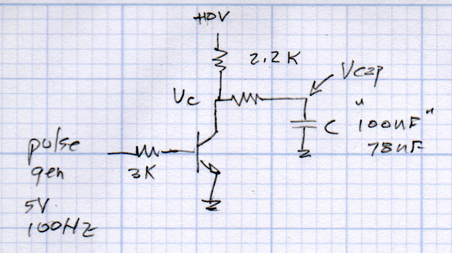
Add cap to transistor switch with R to soften discharge path
- charge vs discharge paths
- calculate time constants
- wire it up
- verify with oscilloscope
The circuit will look like this:
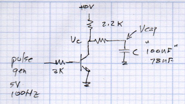
NPN switch – Cap charge-discharge Discussion of parts tolerance: 100 nF caps are really 78 nF
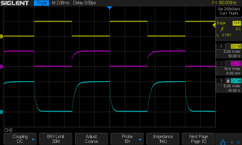
With one cap:
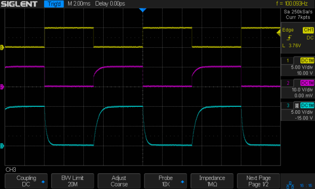
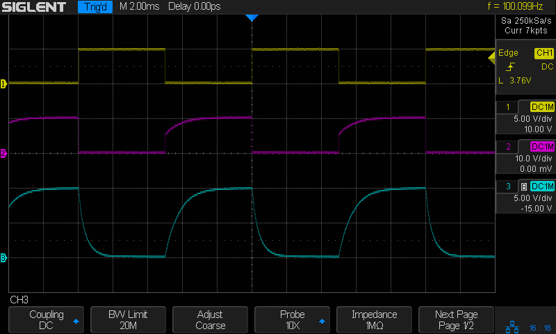
NPN – 100 Hz – 2.2k 2.2k 78nF – Vc Vcap Add another cap for twice the time constant:
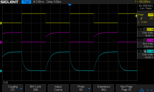
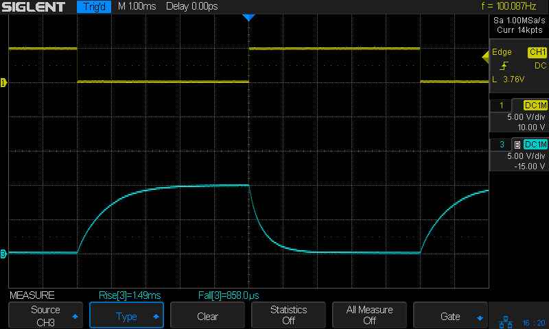
NPN – 100 Hz – 2.2k 2.2k 2x78nF – Vc Vcap Let the scope calculate 10-90% rise time:
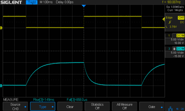
NPN – 100 Hz – 2.2k 2.2k 2x78nF – Vc Vcap – rise fall times Useful relations:
- rise time = 2.2 τ (compare with calculations!)
- rise time = 0.34/BW
Do it on hard mode with the old Tek scope for pedagogic purposes.
That should soak up the better part of four hours!



-
Subscribe
Subscribed
Have a WordPress.com account? Log in now.

