-
Juki TL-2010Q: COB LED Light Bar
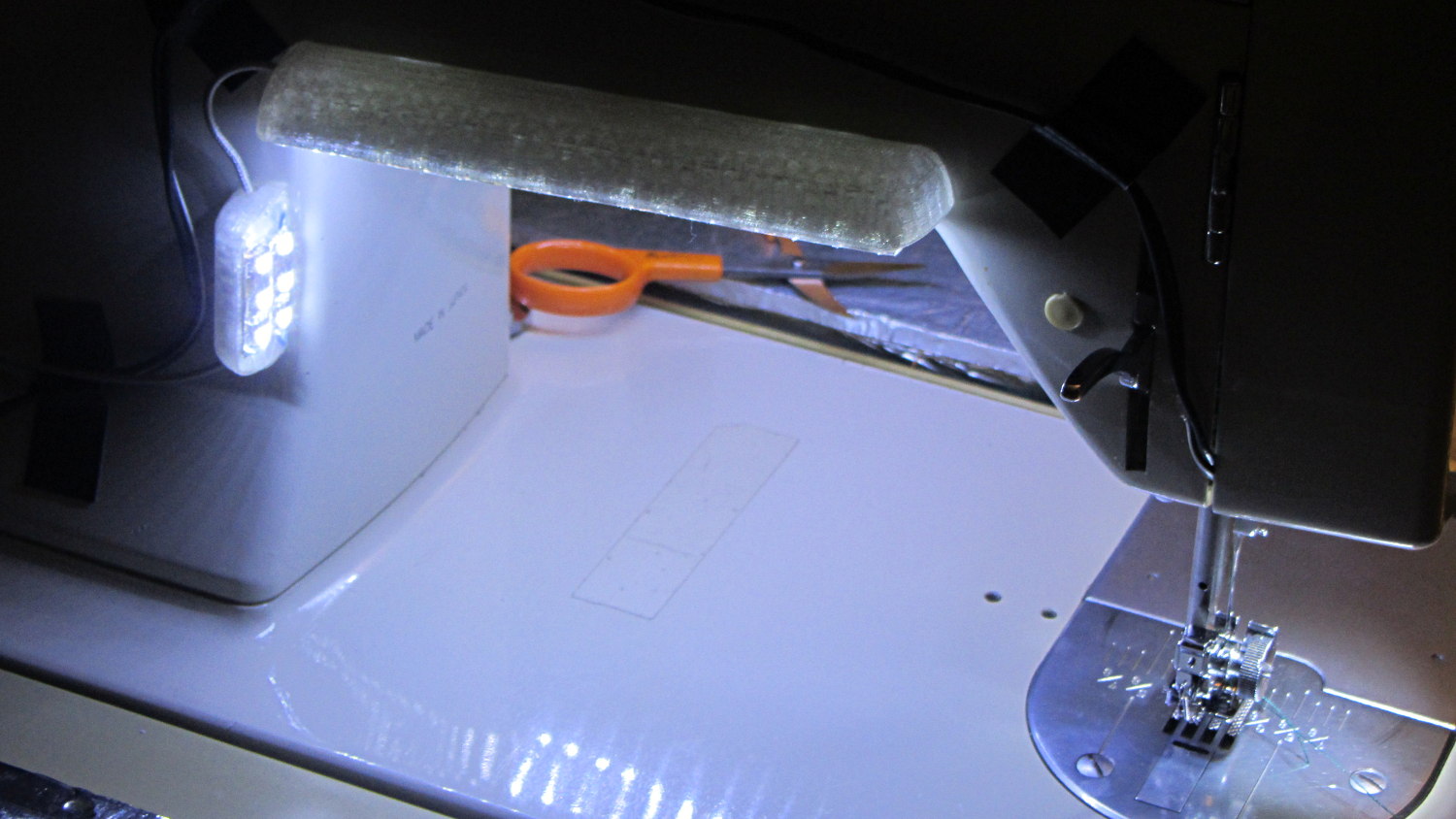
Mary needed more light under the arm of her Juki TL-2010Q sewing machine, so I proposed a 12 V 6 W COB LED module instead of the high-density LED strips I used on her Kenmore 158s:
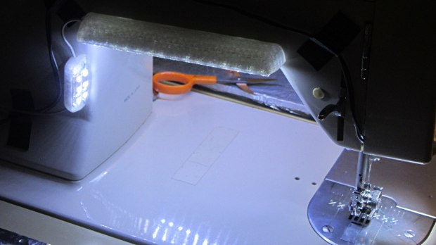
Kenmore 158 Sewing Machine – Cool white LEDs – rear no flash Because the COB LEDs dissipate 6W, far more power than I’m comfortable dumping into a 3D printed structure, I redefined a length of aluminum shelf bracket extrusion to be a heatsink and epoxied the module’s aluminum back plate thereto:
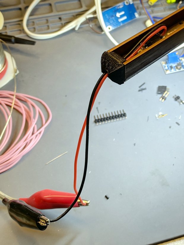
Juki TL-2010Q COB LED – test lighting Unlike the flexible LED strips, the COB LED modules have no internal ballast resistors and expect to run from a constant-current supply. Some preliminary testing showed we’d want less than the maximum possible light output, so a constant-voltage supply and a few ohms of ballast would suffice:

Juki TL-2010Q COB LED – ballast resistor test With all that in hand, the heatsink extrusion cried out for smooth endcaps to control the wires and prevent snagging:

TL-2010Q COB LED Light Bars – end caps – Show layout The central hole in the left cap passes 24 AWG silicone wires from the power supply, with 28 AWG silicone wires snaking down through the L-shaped rectangular cutouts along the extrusion to the LED module’s solder pads.
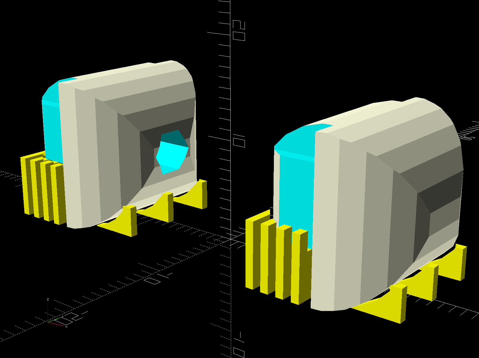
The model includes built-in support:

TL-2010Q COB LED Light Bars – end caps – Build layout Assuming the curved ends didn’t need support / anchors holding them down turned out to be completely incorrect:
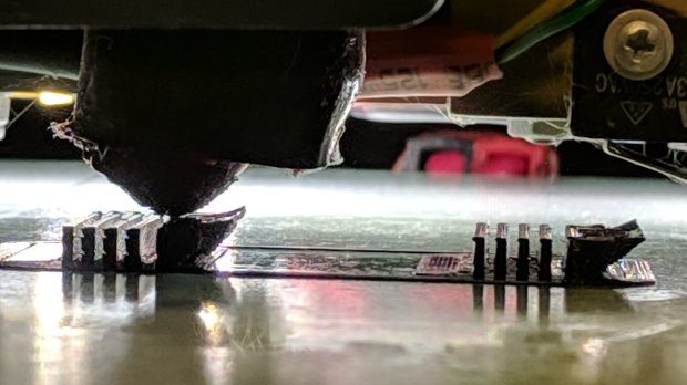
Juki TL-2010Q COB LED – curled endcaps Fortunately, those delicate potato chips lived to tell the tale and, after a few design iterations, everything came out right:

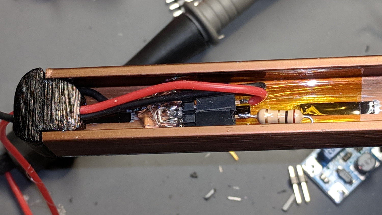
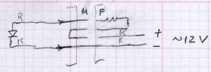
Juki TL-2010Q COB LED – heatsink endcap – internal connections The “connector”, such as it is, serves to make the light bar testable / removable and the ballast resistor tweakable, without going nuts over the details. The left side is an ordinary pin header strip held in place with hot melt glue atop the obligatory Kapton tape, because the heatsink doesn’t get hot enough to bother the glue. The right side is a pair of two-pin header sockets, also intended for PCB use. The incoming power connects to one set and the ballast resistor to the other, thusly:

Juki TL-2010Q COB LED – light bar connector diagram The diagram is flipped top-to-bottom from the picture, but you get the idea. Quick, easy, durable, and butt-ugly, I’d say.
The next step was to mount it on the sewing machine and steal some power, but that’s a story for another day.
The relevant dimensions for the aluminum extrusion:

Aluminum shelf bracket extrusion – dimensions The OpenSCAD source code as a GitHub Gist:
This file contains hidden or bidirectional Unicode text that may be interpreted or compiled differently than what appears below. To review, open the file in an editor that reveals hidden Unicode characters. Learn more about bidirectional Unicode characters// Juki TL-2010Q Sewing Machine – COB LED Light Bars // Ed Nisley – KE4ZNU // 2019-01 /* [Layout Options] */ Layout = "Build"; // [Bracket,Endcap,Show,Build] Wiring = [1,0]; // left and right wire holes BuildSupport = true; /* [Extrusion Parameters] */ ThreadWidth = 0.40; ThreadThick = 0.20; HoleWindage = 0.2; Protrusion = 0.1; //—– // Shelf bracket used as LED heatsink /* [Hidden] */ LEDPlate = [15.0,2.4]; // 2D coords from end of LED BktOuter = [15.9,12.6 + LEDPlate.y]; // 2D coords as seen from end of extrusion BktWalls = [1.3,2.2 + LEDPlate.y]; // … extend base to cover LED BktCap = [2.5,3.0]; BracketPoints = [ [0,0], [BktOuter.x,0], [BktOuter.x,BktOuter.y], [(BktOuter.x – BktCap.x),BktOuter.y], [(BktOuter.x – BktCap.x),(BktOuter.y – BktCap.y)], [(BktOuter.x – BktWalls.x),(BktOuter.y – BktCap.y)], [(BktOuter.x – BktWalls.x),BktWalls.y], [BktWalls.x,BktWalls.y], [BktWalls.x,(BktOuter.y – BktCap.y)], [BktCap.x,(BktOuter.y – BktCap.y)], [BktCap.x,BktOuter.y], [0,BktOuter.y], [0,0] ]; BracketPlugInsert = 10.0; // distance into bracket end WireOD = 1.6; // COB LED jumpers – 24 AWG silicone WireOC = BktOuter.x – 2*BktWalls.x – WireOD; echo(str("Wire OC: ",WireOC)); CableOD = 4.0; // power entry cable CapSides = 2*3*4; //—– // Useful routines module PolyCyl(Dia,Height,ForceSides=0) { // based on nophead's polyholes Sides = (ForceSides != 0) ? ForceSides : (ceil(Dia) + 2); FixDia = Dia / cos(180/Sides); cylinder(r=(FixDia + HoleWindage)/2, h=Height, $fn=Sides); } //—– // Endcap with smooth rounding // Wires = true to punch holes for LED wires module Endcap(Wires = true) { // arc length to flatten inside of cap // not needed to build in normal orientation m = BktOuter.x/2 – sqrt(pow(BktOuter.x/2,2) – pow(BktOuter.x – 2*BktCap.x,2)/4); difference() { translate([0,0,BktOuter.y/2]) // basic endcap shape intersection() { cylinder(d=BktOuter.x,h=BktOuter.y,$fn=CapSides,center=true); rotate([90,0,0]) rotate(180/CapSides) cylinder(d=BktOuter.y,h=BktOuter.x,$fn=CapSides,center=true); } translate([-BracketPlugInsert,0,0]) // extrusion + LED plate Bracket(BracketPlugInsert); if (false) // flatten inner end translate([-BktOuter.y + m,0,BktOuter.y/2]) cube([BktOuter.y,BktOuter.x,BktOuter.y],center=true); if (Wires) { for (j=[-1,1]) // COB LED connections translate([WireOD – BktOuter.x/2,j*WireOC/2,(BktWalls.y + WireOD – Protrusion)/2]) rotate([0,00,0]) cube([BktOuter.x,WireOD + Protrusion,BktWalls.y + WireOD + Protrusion],center=true); translate([0,0,BktOuter.y/2]) // power entry / exit rotate([0,90,0]) translate([0,0,-BktOuter.x]) rotate(180/6) PolyCyl(CableOD,2*BktOuter.x,6); } } } // Totally ad-hoc support structures module Support(Wiring = false) { Spacing = 4*ThreadWidth; NumBars = floor((BktOuter.y/2) / Spacing); echo(str("Support bars: ",NumBars)); color("Yellow") { render() difference() { union() { for (i=[1:NumBars]) // inside extrusion translate([-i*Spacing,0,(BktWalls.y + WireOD)/2]) cube([2*ThreadWidth,BktOuter.x – 0*BktWalls.x,BktWalls.y + WireOD],center=true); if (true) for (j=[-1:1]) // reduce outside curve uplift translate([0.3*BktOuter.y,j*BktOuter.x/3,BktOuter.y/10]) cube([BktOuter.y/3,2*ThreadWidth,BktOuter.y/5],center=true); } minkowski() { // all-around clearance Endcap(Wiring); cube(2.0*ThreadThick,center=true); } if (Wiring) { translate([0,0,BktOuter.y/2]) // remove rubble from wire bore rotate([0,90,0]) translate([0,0,-BktOuter.x]) rotate(180/6) PolyCyl(CableOD,2*BktOuter.x,6); } } if (false) translate([-(BktOuter.x/4 + ThreadWidth),0,ThreadThick/2]) // adhesion pad cube([BktOuter.x/2,BktOuter.x – BktWalls.x,ThreadThick],center=true); // translate([BktOuter.x/3,0,ThreadThick/2]) // adhesion pad // cube([0.3*BktOuter.x,0.7*BktOuter.x,ThreadThick],center=true); if (false) for (j = [-1:1]) // tie pad to bottom of cap translate([-(4*ThreadWidth)/2,j*(BktOuter.x – 2*ThreadWidth)/2,ThreadThick/2]) cube([4*ThreadWidth,2*ThreadWidth,ThreadThick],center=true); } } //—– // Heatsink extrusion + LED plate // Centered on Y with Length extending in +X module Bracket(Length = 10) translate([0,-BktOuter.x/2,0]) rotate([90,0,90]) linear_extrude(height = Length,convexity=3) polygon(points=BracketPoints); //—– // Build things if (Layout == "Bracket") Bracket(); if (Layout == "Endcap") Endcap(); if (Layout == "Show") { translate([BktOuter.x,0,0]) Endcap(Wiring[1]); translate([-BktOuter.x,0,0]) rotate(180) Endcap(Wiring[0]); color("Yellow",0.35) translate([-BktOuter.x/2,0,0]) Bracket(BktOuter.x); } if (Layout == "Build") { translate([BktOuter.y,0,0]) { Endcap(Wiring[0]); if (BuildSupport) Support(Wiring[0]); } translate([-BktOuter.y,0,0]) { Endcap(Wiring[1]); if (BuildSupport) Support(Wiring[1]); } }




-
Subscribe
Subscribed
Have a WordPress.com account? Log in now.

