-
DRV8825 Stepper Driver: Adding a Home Output
The DRV8825 stepper driver chip has a
-Homeoutput going active during the (micro)step corresponding to 45°, where both winding currents equal 71% of the peak value: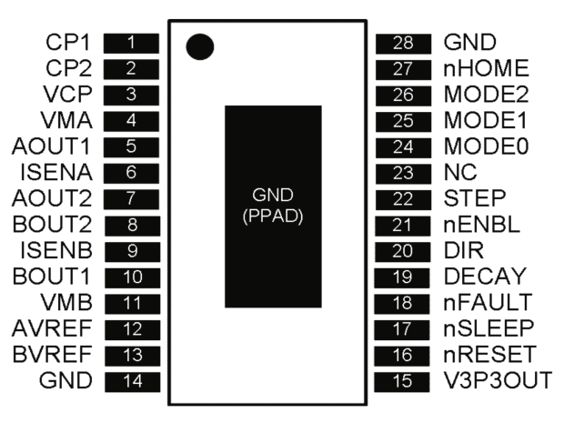
DRV8825 pinout Unfortunately, pin 27 is another unconnected pin on the DRV8825 PCB, without even a hint of a pad for E-Z soldering.
It’s also an open-drain output in need of a pullup, so I globbed on a 1/8 W 10 kΩ resistor in addition to the tiny wire from the IC pad to the left header pin:
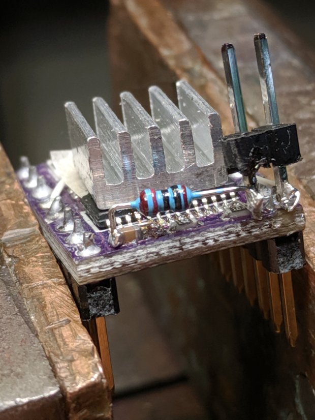
DRV8825 PCB – Home signal output Read it from the right: brown black black red gold. Even in person, the colors don’t look like that, not even a little bit: always measure before installation!
The right header pin is firmly soldered to the PCB ground pin I also used for the 1:8 microstep hack. The whole affair received a generous layer of hot melt glue in the hope of some mechanical stabilization, although hanging a scope probe off those pins can’t possibly end well.
The general idea is to provide a scope sync output independent of the motor speed, so I can look at the current waveforms:

3018 X – Fast – 12V – 140mm-min 1A-div The alert reader will note the pulse occurs on the down-going side of the waveforms, which means I have the current probes clipped on backwards or, equivalently, on the wrong wire. The point is to get a stable sync, so it’s all good no matter which way the current goes.
-
Subscribe
Subscribed
Have a WordPress.com account? Log in now.

