-
Bamboo Bee Tunnel Nests: In Use!
Just over a month after mounting bamboo bee tunnel nest bundles here & there around the house & yard, they have occupants!
One of the bundles of small (a few mm ID) stalks on the kitchen window:
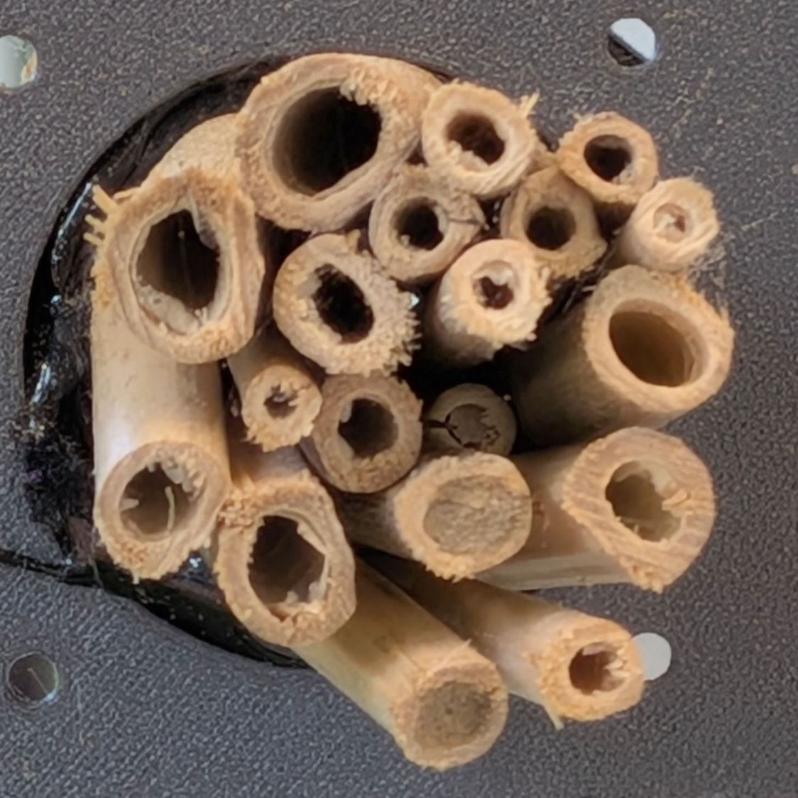
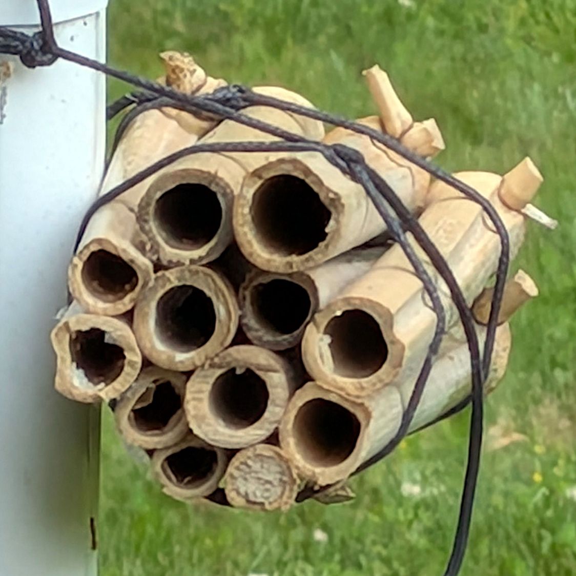
Bee Tunnel Nest – small A Another bundle of small stalks on a window a dozen feet away:
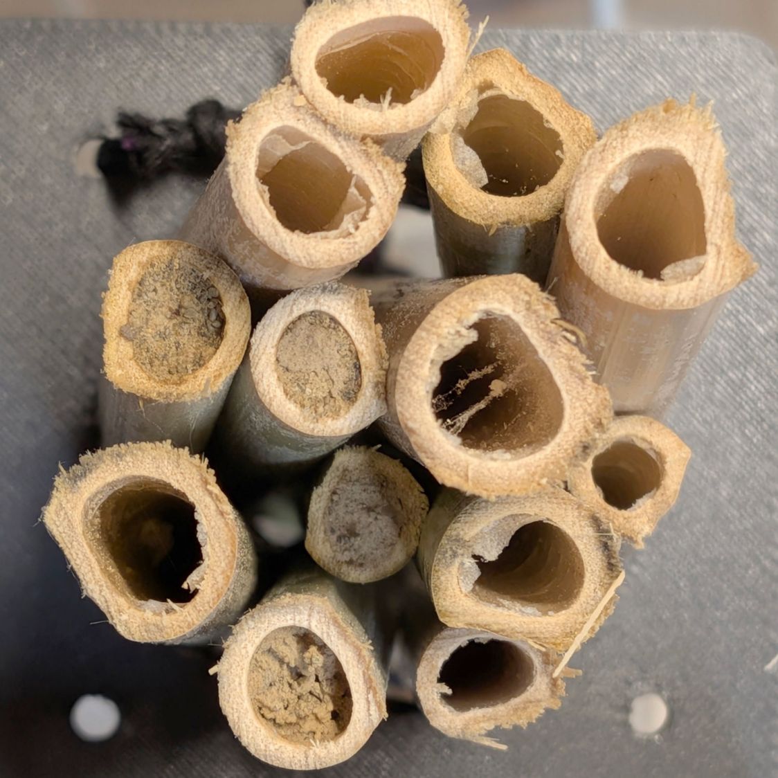
Bee Tunnel Nest – small B A bundle of medium (five to ten mm ID) stalks lashed to a downspout:
Bee Tunnel Nest – medium Unlike the mud dauber wasps decorating our previous house, these little bees dart in and out without announcing their presence: we’ve never seen them at work.
Assuming a single bee works on each bundle, she apparently starts with the lowest stalk and moves upward after filling & capping it.
Larger bees have yet to discover the bundles of larger stalks out on the trees, but … so far, so good!
-
Subscribe
Subscribed
Already have a WordPress.com account? Log in now.
