-
Mini-lathe Metric Threading: Stackable Change Gear Generator
Although OpenSCAD’s MCAD library includes a gear generator, I don’t profess to understand the relations between reality and its myriad parameters, plus I vaguely recall it has a peculiar definition for Diametral Pitch (or some such). Rather than fiddle with all that, I start with an SVG outline from Inkscape’s Gears extension and go all 3D on it.
So, the “gear blank” looks like this after extruding the SVG:

Mini-lathe change gear – 42 tooth – SVG import Producing this is a lot easier in OpenSCAD than in real life:

Mini-lathe change gear – 42 tooth – solid model OpenSCAD centers the blank’s bounding box at XY=0, which won’t be exactly on the bore centerline for gears with an odd number of teeth. One tooth sits at 0° and two teeth bracket 180°, so the bounding box will be a little short on one side
A reference for gear nomenclature & calculations will come in handy.
For a 21 tooth module 1 gear, which should be pretty close to the worst case in terms of offset:
- Pitch dia = d = 21 × 1 = 21 mm
- Tip dia = da = d + 2m = 23 mm
- Tip radius = da/2 = 11.5 mm
- Tooth-to-tooth angle = 360/21 = 17.143°
- Radius to tangent across adjacent teeth = 11.5 × cos 17.143°/2 = 11.372 mm
An actual metal 21 tooth gear measures 22.87 mm across a diameter, dead on what those numbers predict: 11.5 + 11.372 = 22.872 mm.
So the bounding box will be 11.5 mm toward the tooth at 0° and 11.372 mm toward the gap at 180°. The offset will be half that, with the tooth at 0° sitting 0.063 mm too close to the origin. Gears with more teeth will have smaller errors.
Given that we’re dealing with a gear “machined” from plastic goo, that’s definitely close enough:

Mini-Lathe change gears – 1 mm – 45-50-45-60 That’s an earlier version with the debossed legend.
The code can also generate stacked gears for the BC shaft in the middle:
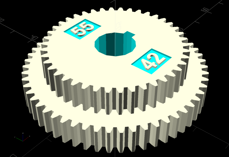
Mini-lathe change gear – 42-55 tooth stacked – solid model In principle, the key locking the gears together isn’t needed and the bore could fit the inner shaft, rather than the keyed bushing, but then you’d (well, I’d) be at risk of losing the bushing + key in one easy operation.
So it’s better to go with the bushing:
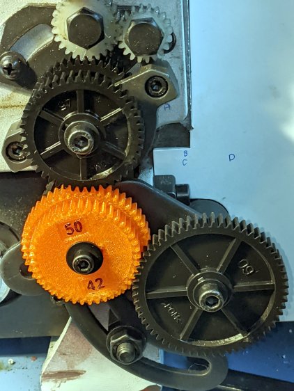
Mini-Lathe change gears – stacked 50-42 – installed Now, to cut some threads!
The OpenSCAD source code as a GitHub Gist:
This file contains hidden or bidirectional Unicode text that may be interpreted or compiled differently than what appears below. To review, open the file in an editor that reveals hidden Unicode characters. Learn more about bidirectional Unicode characters// LMS Mini-Lathe // Change gears with stacking // Generate SVG outlines with Inkscape's Gear extension // Ed Nisley – KE4ZNU // 2020-05 /* [Gears] */ TopGear = 0; // zero for single gear BottomGear = 42; /* [Hidden] */ ThreadThick = 0.25; ThreadWidth = 0.40; HoleWindage = 0.2; function IntegerMultiple(Size,Unit) = Unit * ceil(Size / Unit); Protrusion = 0.1; // make holes end cleanly Dir = ""; // empty string for current directory /* [Dimensions] */ ShaftOD = 12.0; ShaftSides = 4*3; GearThick = 7.75; Keyway = [3.5 + HoleWindage,3.0 + HoleWindage,3*GearThick]; // x on radius, y on perim, z on axis LegendThick = 2*ThreadThick; LegendZ = (TopGear ? 2*GearThick : GearThick) – LegendThick; LegendRecess = [10,7,LegendThick]; LegendEnable = (TopGear == 0 && BottomGear > 41) || (TopGear > 41); //———————- // Useful routines // Enlarge holes to prevent geometric shrinkage // based on nophead's polyholes // http://hydraraptor.blogspot.com/2011/02/polyholes.html // http://www.thingiverse.com/thing:6118 module PolyCyl(Dia,Height,ForceSides=0) { Sides = (ForceSides != 0) ? ForceSides : (ceil(Dia) + 2); FixDia = Dia / cos(180/Sides); cylinder(r=(FixDia + HoleWindage)/2, h=Height, $fn=Sides); } //———————– // Build it! union() { difference() { union() { linear_extrude(GearThick,center=false,convexity=5) import(file=str(Dir,"Change Gear – ",BottomGear," teeth.svg"), center=true); if (TopGear) translate([0,0,GearThick]) linear_extrude(GearThick,center=false,convexity=5) import(file=str(Dir,"Change Gear – ",TopGear," teeth.svg"), center=true); } rotate(180/ShaftSides) translate([0,0,-Protrusion]) PolyCyl(ShaftOD,3*GearThick); translate([ShaftOD/2,0,Keyway.z/2 – Protrusion]) cube(Keyway,center=true); if (LegendEnable) { translate([0,1.1*ShaftOD,LegendZ + LegendRecess.z/2]) cube(LegendRecess + [0,0,Protrusion],center=true); if (TopGear) { translate([0,-1.1*ShaftOD,LegendZ + LegendRecess.z/2]) cube(LegendRecess + [0,0,Protrusion],center=true); } } } if (LegendEnable) translate([0,0,LegendZ – Protrusion]) linear_extrude(height=LegendThick + Protrusion,convexity=10) { translate([-0*2.5,1.1*ShaftOD]) rotate(-0*90) text(text=str(BottomGear),size=5,font="Arial:style:Bold",halign="center",valign="center"); if (TopGear) translate([-0*2.5,-1.1*ShaftOD]) rotate(-0*90) text(text=str(TopGear),size=5,font="Arial:style:Bold",halign="center",valign="center"); } }
-
Subscribe
Subscribed
Have a WordPress.com account? Log in now.

