-
Glass Tiles: 2×2 Matrix
Start with a single cell holding a glass tile over a WS2812 RGB LED:

Glass Tile – 1×1 cell test – purple phase A bit of OpenSCAD tinkering produces a simple 2×2 array with square interiors as a test piece:
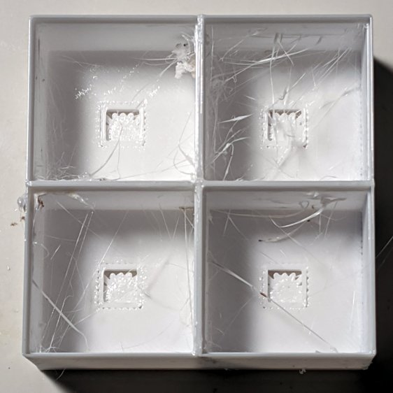
Glass Tile – 2×2 – PETG strings The excessive stringing and the booger in the upper-left cell come from absurdly thin infill tucked into the too-thin walls; Slic3r doesn’t (seem to) have a “minimum infill width” setting and it’ll desperately try to fit infill between two nearly adjacent perimeter threads.
The little support spiders under the LED PCB recesses snapped right out, though, so I got that part right:

Glass Tile – 2×2 – support spiders The perimeter threads around the LED aperture aren’t quite fused, because it was only one layer thick and that’s not enough.
A quick test with two LEDs showed the white PETG let far too much light bleed between the cells, which was no surprise from the single cell test piece.
Fortunately, it’s all parametric, so a bit more tinkering produced a slightly chunkier matrix with a base for an Arduino Nano and M3 threaded brass inserts for the screws holding it together:

Glass Tile Frame – 2×2 – Arduino Nano base – solid model Those two parts require about three hours of printing, much faster than I could produce them by milling pockets into aluminum or black acrylic slabs, and came out with minimal stringing.
A little cleanup, some epoxy work, and a few dabs of solder later:

Glass Tile – 2×2 – Arduino wiring An initial lamp test showed the white-ish glass tiles aren’t all quite the same color:

Glass Tile – 2×2 – white color variation I thought it was an LED color variation, too, but the slightly blue tint in the lower left corner followed the tile.
The blurred horizontal strip across the middle is adhesive tape holding the tiles in place; I was reluctant to glue them in before being sure this whole thing would work. A peek into the future, though, shows it’s got potential:

Glass Tile – 2×2 – first two units They do give off a definite Windows logo vibe, don’t they?
The OpenSCAD source code as a GitHub Gist:
This file contains hidden or bidirectional Unicode text that may be interpreted or compiled differently than what appears below. To review, open the file in an editor that reveals hidden Unicode characters. Learn more about bidirectional Unicode characters// Illuminated Tile Grid // Ed Nisley – KE4ZNU // 2020-05 /* [Configuration] */ Layout = "Build"; // [Cell,CellArray,MCU,Base,Show,Build] Shape = "Square"; // [Square, Pyramid, Cone] Cells = [2,2]; CellDepth = 15.0; Support = true; Inserts = true; /* [Hidden] */ ThreadThick = 0.25; ThreadWidth = 0.40; HoleWindage = 0.2; function IntegerMultiple(Size,Unit) = Unit * ceil(Size / Unit); Protrusion = 0.1; // make holes end cleanly ID = 0; OD = 1; LENGTH = 2; Tile = [25.0 + 0.1,25.0 + 0.1,4.0]; WallThick = 3*ThreadWidth; Flange = [4*ThreadWidth,4*ThreadWidth,0]; // ridge supporting tile Separator = [3*ThreadWidth,3*ThreadWidth,Tile.z – 1]; // between tiles Screw = [3.0,6.0,3.5]; // M3 SHCS, OD=head, LENGTH=head Insert = [3.0,4.2,8.0]; // threaded brass insert PCB = [15.0,8.0,2.5]; LED = [5.0 + 2*HoleWindage,5.0 + 2*HoleWindage,1.0]; LEDOffset = [0.0,(PCB.y – LED.y)/2 – 0.5,0.0]; // slight offset from +Y PCB edge CellOAL = [Tile.x,Tile.y,0] + Separator + [0,0,CellDepth] + [0,0,WallThick] + [0,0,PCB.z]; ArrayOAL = [Cells.x*CellOAL.x,Cells.y*CellOAL.y,CellOAL.z]; // just the LED cells BlockOAL = ArrayOAL + [2*WallThick,2*WallThick,0]; // LED cells + exterior wall echo(str("Block OAL: ",BlockOAL)); InsertOC = ArrayOAL – [Insert[OD],Insert[OD],0] – [2*WallThick,2*WallThick,0]; echo(str("Insert OC: ",InsertOC)); TapeThick = 1.0; Arduino = [44.0,18.0,8.0 + TapeThick]; // Arduino Nano to top of USB Mini-B plug USBPlug = [15.0,11.0,8.5]; // USB Mini-B plug insulator USBOffset = [0,0,5.5]; // offset from PCB base WiringBay = [BlockOAL.x – 4*WallThick,38.0,3.0]; PlateOAL = [BlockOAL.x,BlockOAL.y,WallThick + Arduino.z + WiringBay.z]; echo(str("Base Plate: ",PlateOAL)); //———————— module PolyCyl(Dia,Height,ForceSides=0) { // based on nophead's polyholes Sides = (ForceSides != 0) ? ForceSides : (ceil(Dia) + 2); FixDia = Dia / cos(180/Sides); cylinder(d=(FixDia + HoleWindage),h=Height,$fn=Sides); } //———————– // Base and optics in single tile module LEDCone() { hull() { translate([0,0,CellDepth + Tile.z/2]) cube(Tile – [Flange.x,Flange.y,0],center=true); if (Shape == "Square") { translate([0,0,LED.z/2]) cube([Tile.x,Tile.y,LED.z] – [Flange.x,Flange.y,0],center=true); } else if (Shape == "Pyramid") { translate([0,0,LED.z/2]) cube(LED,center=true); } else if (Shape == "Cone") { translate([0,0,LED.z/2]) cylinder(d=1.5*LED.x,h=LED.z,center=true); } else { echo(str("Whoopsie! Invalid Shape: ",Shape)); cube(5); } } } // One complete LED cell module LEDCell() { difference() { translate([0,0,CellOAL.z/2]) cube(CellOAL,center=true); translate([0,0,CellOAL.z – Separator.z + Tile.z/2]) cube(Tile,center=true); translate([0,0,PCB.z + WallThick]) LEDCone(); cube([LED.x,LED.y,CellOAL.z],center=true); translate(-LEDOffset + [0,0,PCB.z/2 – Protrusion/2]) cube(PCB + [0,0,Protrusion],center=true); } if (Support) color("Yellow") render() translate(-LEDOffset) { // translate([0,0,ThreadThick/2]) // cube([PCB.x – 2*ThreadWidth,PCB.y – 2*ThreadWidth,ThreadThick],center=true); intersection() { translate([0,0,(PCB.z – ThreadThick)/2]) cube([PCB.x – 2*ThreadWidth,PCB.y – 2*ThreadWidth,PCB.z – ThreadThick],center=true); union() { for (a=[0:22.5:359]) rotate(a) translate([PCB.x/2,0,PCB.z/2]) cube([PCB.x,2*ThreadWidth,PCB.z],center=true); } } } } // The whole array of cells module CellArray() { difference() { union() { translate([CellOAL.x/2 – Cells.x*CellOAL.x/2,CellOAL.y/2 – Cells.y*CellOAL.y/2,0]) for (i=[0:Cells.x – 1], j=[0:Cells.y – 1]) translate([i*CellOAL.x,j*CellOAL.y,0]) LEDCell(); if (Inserts) // bosses for (i=[-1,1], j=[-1,1]) translate([i*InsertOC.x/2,j*InsertOC.y/2,0]) rotate(180/8) cylinder(d=Insert[OD] + 3*WallThick,h=Insert[LENGTH],$fn=8); } if (Inserts) // holes for (i=[-1,1], j=[-1,1]) translate([i*InsertOC.x/2,j*InsertOC.y/2,-Protrusion]) rotate(180/8) PolyCyl(Insert[OD],Insert[LENGTH] + WallThick + Protrusion,8); } difference() { translate([0,0,CellOAL.z/2]) cube(BlockOAL,center=true); translate([0,0,CellOAL.z]) cube(ArrayOAL + [0,0,2*CellOAL.z],center=true); } } // Arduino bounding box // Origin at center bottom of PCB module Controller() { union() { translate([0,0,Arduino.z/2]) cube(Arduino,center=true); translate([Arduino.x/2 – Protrusion,-USBPlug.y/2,USBOffset.z + TapeThick – USBPlug.z/2]) cube(USBPlug + [Protrusion,0,0],center=false); } } // Baseplate module BasePlate() { difference() { translate([0,0,PlateOAL.z/2]) cube(PlateOAL,center=true); translate([0,0,WallThick]) Controller(); translate([0,0,WallThick + PlateOAL.z/2]) cube([Arduino.x – 2*2.0,WiringBay.y,PlateOAL.z],center=true); translate([0,0,PlateOAL.z – WiringBay.z + WiringBay.z/2]) cube(WiringBay + [0,0,2*Protrusion],center=true); for (i=[-1,1], j=[-1,1]) translate([i*InsertOC.x/2,j*InsertOC.y/2,-Protrusion]) rotate(180/8) { PolyCyl(Screw[ID],2*PlateOAL.z,8); PolyCyl(Screw[OD],Screw[LENGTH] + 4*ThreadThick + Protrusion,8); } translate([0,0,ThreadThick-Protrusion]) cube([17.0,45,2*ThreadThick],center=true); } linear_extrude(height=2*ThreadWidth + Protrusion) { translate([1,0,-Protrusion]) rotate(-90) mirror([1,0,0]) text(text="Ed Nisley",size=6,font="Arial:style:Bold",halign="center"); translate([-6.5,0,-Protrusion]) rotate(-90) mirror([1,0,0]) text(text="softsolder.com",size=4.5,font="Arial:style:Bold",halign="center"); } if (Support) color("Yellow") for (i=[-1,1], j=[-1,1]) translate([i*InsertOC.x/2,j*InsertOC.y/2,0]) for (a=[0:45:135]) rotate(a) translate([0,0,(Screw[LENGTH] – ThreadThick)/2]) cube([Screw[OD] – 2*ThreadWidth,2*ThreadWidth,Screw[LENGTH] – ThreadThick],center=true); } //———————– // Build things if (Layout == "Cell") LEDCell(); else if (Layout == "CellArray") CellArray(); else if (Layout == "MCU") Controller(); else if (Layout == "Base") BasePlate(); else if (Layout == "Show") { translate([0,0,PlateOAL.z + 10]) CellArray(); BasePlate(); } else if (Layout == "Build") { translate([0,0.6*BlockOAL.y,0]) CellArray(); translate([0,-0.6*BlockOAL.y,0]) rotate(90) BasePlate(); }
-
Subscribe
Subscribed
Have a WordPress.com account? Log in now.

