-
Mini-Lathe Ball Drilling Fixture
Despite successfully drilling holes in a few plastic balls, I wanted a somewhat less terrifying setup than this:
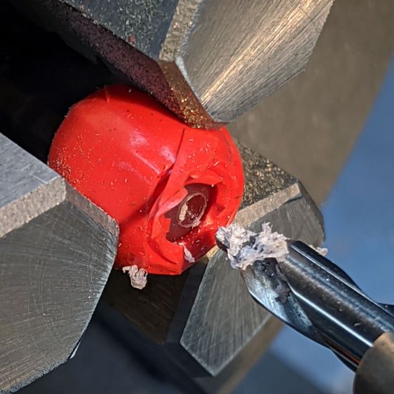
Micromark Ball Vise – lathe ball hack The stiffness of the bike helmet mirror mount suggested a similar clamp would have enough griptivity to immobilize the ball while cutting it in the lathe:
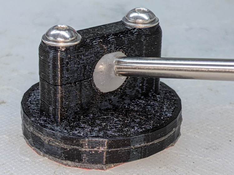
Helmet Mirror Mount – 10 mm ball Building the clamp around the lathe’s three-jaw lathe chuck eliminates the need for screws / washers / inserts:
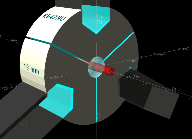
Lathe Ball Fixture – 19 mm – Show The Ah-ha! moment came when I realized the fixture can expose half of the ball’s diameter for drilling while clamping 87% of its diameter, because 0.5 = sin 30° and 0.87 = cos 30°:
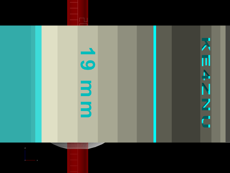
Lathe Ball Fixture – 19 mm – Show – front orthogonal That’s an orthogonal view showing 13% of the ball radius sticking out of the fixture; it’s 6% of the diameter.
Which looks like this in real life:

Lathe Ball Fixture – 19 mm – sections with ball The socket is offset toward the tailstock end of the clamp (on the right in the picture) to expose half its diameter flush with the surface perpendicular to the lathe axis. The other side necks down into a cylinder of the same diameter to clear the drill bit.
This works nicely until the ball diameter equals the chuck jaw’s 20 mm length, whereupon larger balls protrude into the chuck body’s spindle opening. Although I haven’t yet built one, the 25 mm balls in my Box o’ Bearings should fit, with exceedingly sissy cuts required for large holes.
The fixture doesn’t require support material, because the axial holes eliminate the worst of the overhang. Putting the tailstock side flat on the platform gives it the best-looking surface:
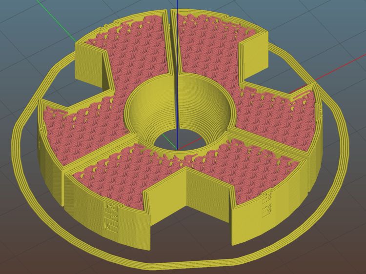
Lathe Ball Fixture – 19 mm – Slic3r – equator The kerf between the segments ensures the jaws can apply pressure to the ball, whereupon the usual
crappyserrated 3D printed surface firmly grabs it.The fixture is a slip fit on the chuck jaws:
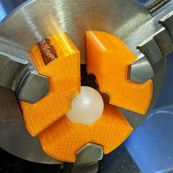
Lathe Ball Fixture – 19 mm – installed Tightening the jaws shoves them all the way into the fixture’s slots and clamps the ball:
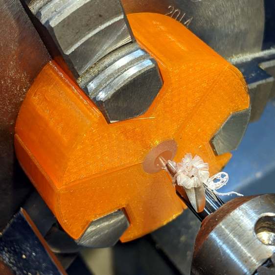
Lathe Ball Fixture – 19 mm – center drill Overtightening the chuck will (probably) compress the ball around the drill, which will (best case) give you slightly oversize holes or (worst case) cause the ball to seize / melt around the drill bit, so sleaze up to the correct hole diameter maybe half a millimeter at a time:
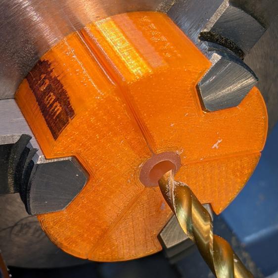
Lathe Ball Fixture – 19 mm – 6 mm drill That fixture exposes 9.5 mm = 19/2 of the ball. The drill makes a 6 mm hole to fit the telescoping shaft seen above.
Obviously, you must build a custom fixture for every ball diameter in your inventory, which is no big deal when you have a hands-off manufacturing process. Embossing the diameter into the fixture helps match them, although the scribbled Sharpie isn’t particularly elegant.
The OpenSCAD source code as a GitHub Gist:
This file contains hidden or bidirectional Unicode text that may be interpreted or compiled differently than what appears below. To review, open the file in an editor that reveals hidden Unicode characters. Learn more about bidirectional Unicode characters// Lathe Ball Drilling Fixture // Ed Nisley KE4ZNU 2020-11 /* [Layout options] */ Layout = "Build"; // [Build, Show, Body, Jaws] BallDia = 10.0; // [5.0:0.5:25.0] /* [Extrusion parameters] */ /* [Hidden] */ ThreadThick = 0.25; ThreadWidth = 0.40; HoleWindage = 0.2; function IntegerMultiple(Size,Unit) = Unit * ceil(Size / Unit); function IntegerLessMultiple(Size,Unit) = Unit * floor(Size / Unit); Protrusion = 0.1; // make holes end cleanly inch = 25.4; ID = 0; OD = 1; LENGTH = 2; //* [Basic dimensions] */ Chuck = [21.0,100.0,20.0]; // chuck bore, OD, jaw length Jaw = [Chuck[LENGTH],15.0,12.0]; // jaw free length, base width, first step radius JawInclAngle = 112; // < 120 degrees for clearance! JawAngle = JawInclAngle/2; // angle from radius WallThick = 5.0; // min wall thickness Kerf = 0.75; // space between clamp blocks ClampSides = 8*(2*3); ClampBore = BallDia/2; // clear bore through clamp ClampAngle = asin(ClampBore/BallDia); // angle from lathe axis to clamp front Plate = [ClampBore, BallDia + 2*WallThick + 2*Jaw.z, Jaw.x]; LegendDepth = 1*ThreadWidth; ShaftOD = 3.6; // sample shaft ShowGap = 1.5; //———————- // Chuck jaws // Real jaws have a concave radiused tip we simply ignore module ChuckJaws(l=Jaw.x,r=10) { for (a=[0:120:240]) rotate(a) linear_extrude(height=l) translate([r,0]) difference() { translate([Chuck[OD]/4,0]) square([Chuck[OD]/2,Jaw.y],center=true); for (i=[-1,1]) rotate(i*(90 – JawAngle)) translate([-Jaw.z/2,0]) square([Jaw.z,2*Jaw.y],center=true); } } //———————- // Clamp body module ClampBlocks() { difference() { cylinder(d=Plate[OD],h=Plate[LENGTH],$fn=ClampSides); // main disk translate([0,0,-Protrusion]) // central bore cylinder(d=ClampBore,h=2*Plate[LENGTH],$fn=ClampSides); for (a=[0:120:240]) // kerf slits rotate(60 + a) translate([Plate[OD]/2,0,Protrusion]) cube([Plate[OD],Kerf,2*Plate[LENGTH]],center=true); translate([0,0,BallDia/2 * cos(ClampAngle)]) // ball socket sphere(d=BallDia,$fn=ClampSides); for (a=[0:120:240]) { // legend rotate(4.5*360/ClampSides + a) translate([Plate[OD]/2 – LegendDepth,0,Plate[LENGTH]/2]) rotate([0,90,0]) linear_extrude(height=LegendDepth + Protrusion,convexity=10) mirror([0,0,0]) text(text=str(BallDia," mm"),size=2.5,spacing=1.20,font="Arial:style:Bold",halign="center",valign="center"); rotate(-4.5*360/ClampSides + a) translate([Plate[OD]/2 – LegendDepth,0,Plate[LENGTH]/2]) rotate([0,90,0]) linear_extrude(height=LegendDepth + Protrusion,convexity=10) mirror([0,0,0]) text(text="KE4ZNU",size=2.5,spacing=1.20,font="Arial:style:Bold",halign="center",valign="center"); } } } //———————- // Clamp with jaw cutouts module ClampBody() { difference() { ClampBlocks(); translate([0,0,-Protrusion]) ChuckJaws(l=Jaw.x + 2*Protrusion,r=BallDia/2 + WallThick); } } //———————- // Lash it together if (Layout == "Body") { ClampBlocks(); } if (Layout == "Jaws") { ChuckJaws(); } if (Layout == "Build") { ClampBody(); } if (Layout == "Show") { ClampBody(); color("ivory",0.2) ChuckJaws(r=BallDia/2 + WallThick + ShowGap); // move out for E-Z viewing color("red",0.4) translate([0,0,-Jaw.x/2]) cylinder(d=ShaftOD,h=2*Jaw.x,$fn=ClampSides,center=false); color("white",0.5) translate([0,0,BallDia/2 * cos(ClampAngle)]) // ball socket sphere(d=BallDia,$fn=ClampSides); } The dimension doodles, including some notions that didn’t work:

Lathe Ball Clamp – dimension doodles
-
Subscribe
Subscribed
Have a WordPress.com account? Log in now.

