-
Auvon TENS/EMS: Lead Identification
One of Santa’s myriad helpers recently handed me an Auvon AS8016 TENS/EMS Unit. The manual is, shall we say, light on tech details, but some casual searching turns up the general specs for medical-grade units found in physical therapy offices, plus adjacent Rule 34 compliant (i.e. NSFW) offerings.
Being that type of guy, I had to look at the electricity. Somewhat to my surprise, the reference load turns out to be a pure 500 Ω resistance, which is easy enough to cobble up from a pair of 1 kΩ resistors:
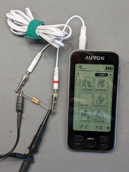
Auvon AS8016 – test setup The alligator clips crunched around the 2 mm pins are not appropriate for even a brutal e-stim session; they’re from the Small Drawer of Test Connectors, to which they shall return unblooded.
The red Sharpie highlight around one pin identifies the center conductor of the two-wire cable, as determined by simple continuity testing:
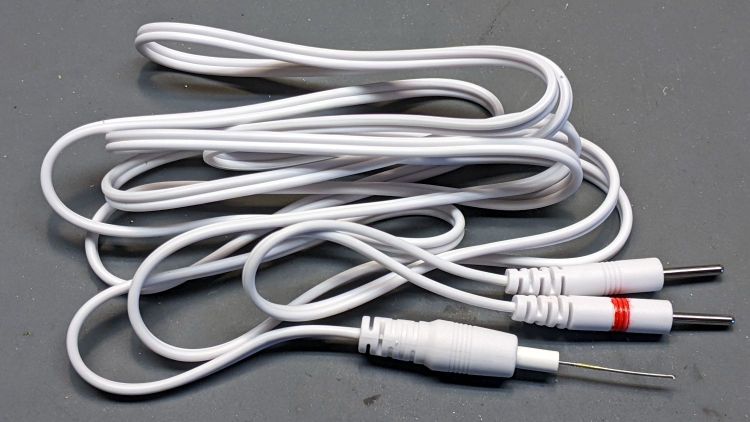
Auvon AS8016 – marked cable The 22 mil = 0.5 mm wire (from the Little Tin o’ Snippets) fits snugly into the coaxial connector’s center contact; one could probably slip a rounded shim between the shell and the outer contact, perhaps to debug an intermittent connection. Note that the connectors on both ends of the wires are not standardized among various TENS/EMS manufacturers.
The AS8016 has two pairs of connectors:

Auvon AS8016 – wire jacks The
A1andA2jacks are wired in parallel, as are theB1andB2jacks, with theApair galvanically isolated from theBpair. You can set the modes / programs / pulse parameters differently forAandB. Although the manual doesn’t mention it, using theAandBchannels (perhaps with the same settings) prevents a galvanic connection (and thus any current) from flowing between theAandBelectrodes; this seems important for electrode pairs placed on opposite sides of your body to prevent current through your heart.The pulses have no DC component, so the actual wire polarity doesn’t really matter, but a foolish consistency definitely simplifies going back to re-measure things. Subsequent waveforms show the voltage with respect to the unmarked (outer) conductor.
Suppressing the DC bias prevents ionic migration between / under the electrode pads. The classic RC-equivalent output circuit uses a series capacitor, resulting in an asymmetric pulse waveform with zero net DC voltage:

Capacitor Coupled Pulse There’s no DC path between the center and outer conductors, but in this day and age the circuitry could be a completely isolated bipolar FET driver:

Auvon M01 Pulse With all that sorted out, I can make measurements!
-
Subscribe
Subscribed
Already have a WordPress.com account? Log in now.
 The Smell of Molten Projects in the Morning