Ed Nisley's Blog: Shop notes, electronics, firmware, machinery, 3D printing, laser cuttery, and curiosities. Contents: 100% human thinking, 0% AI slop.
They’re also accepting our 14th Edition of the Encylopædia Britannica (back when folks realized global war was a thing, but before knowing the recently concluded horror was the first), two dozen Tom Swift Jr books (largely responsible for much of the rest of my life), three years of LIFE magazines from the mid-1940s needing no further description, and a few other goodies:
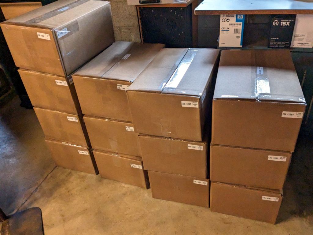
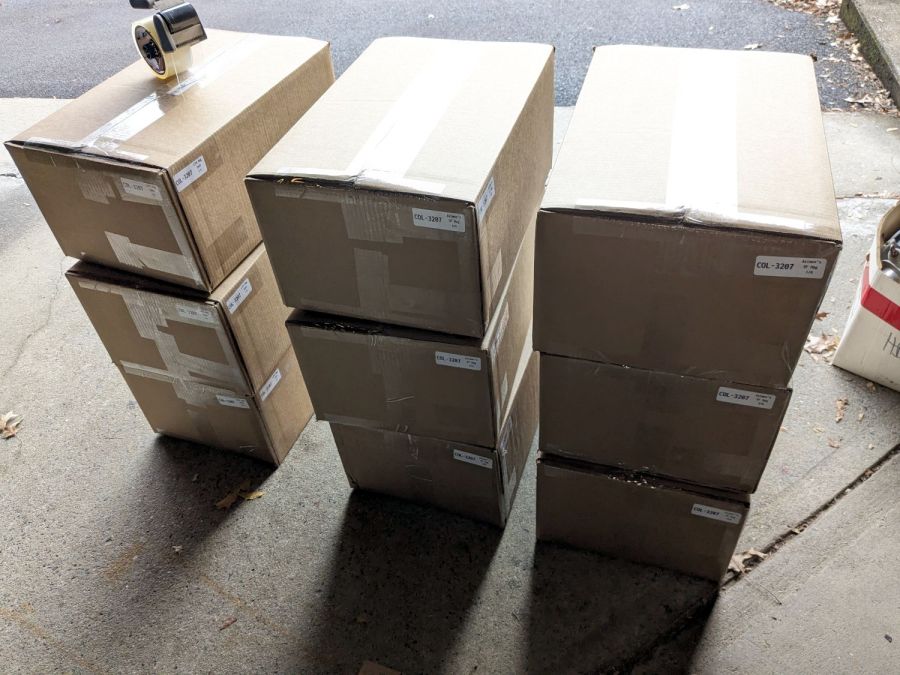
Archive boxes – B
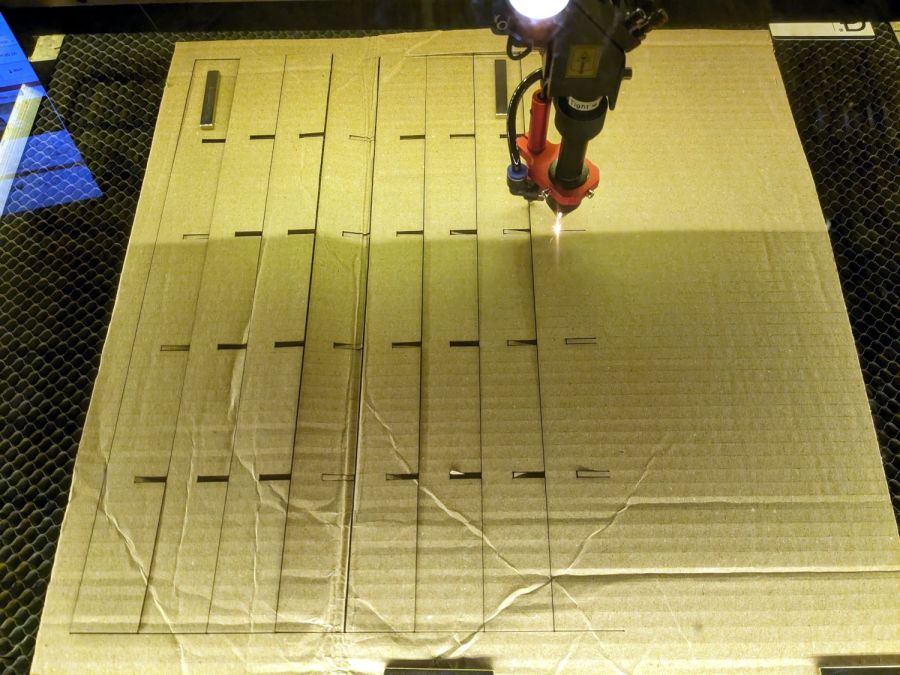
They want boxes packed as solidly as possible to withstand shipping & warehousing, so I converted nearly all of my scrap cardboard into bracing and padding:
Archive boxes – cutting gridwork
The grids are Tray Inserts generated at festi.info:
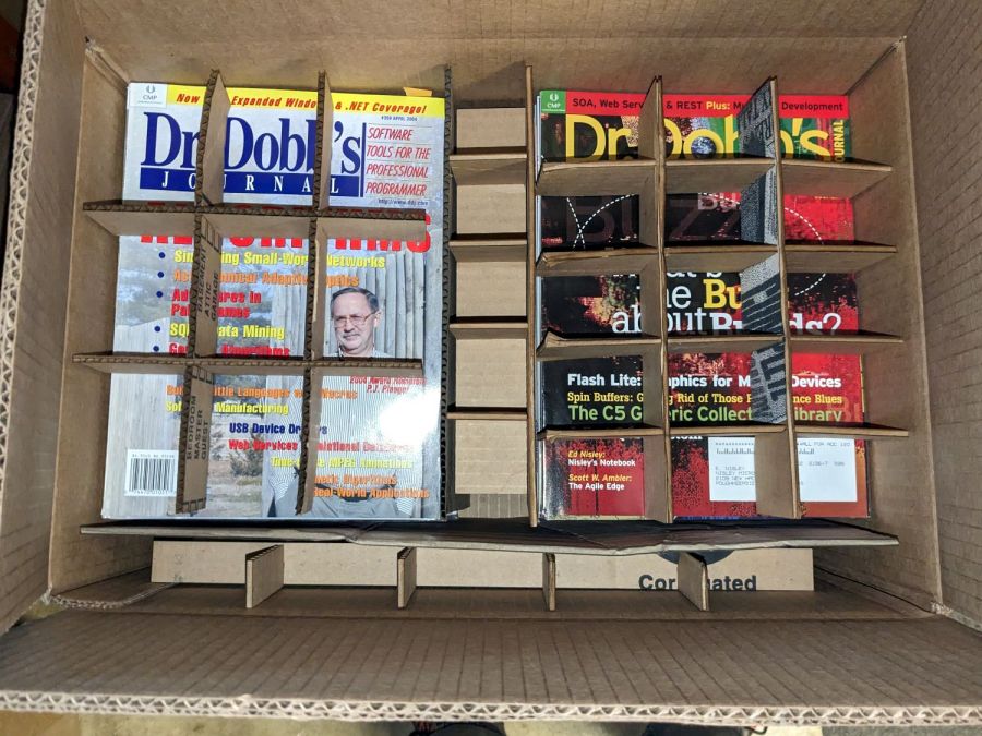
Archive boxes – internal bracing
Here, try one yourself:
TrayInsert – sample QR code
That will set up a grid filling the gap between two stacks of magazines in the Archive’s standard 12×18×8 inch box. You’ll also want simple rectangles for the sides & tops, but those are easy.
They preferred the laser cutter’s inevitable campfire smell to smashed boxes full of crumpled magazines. AFAICT, you might be able to crush the box, but if you did the magazines wouldn’t have survived anyway.
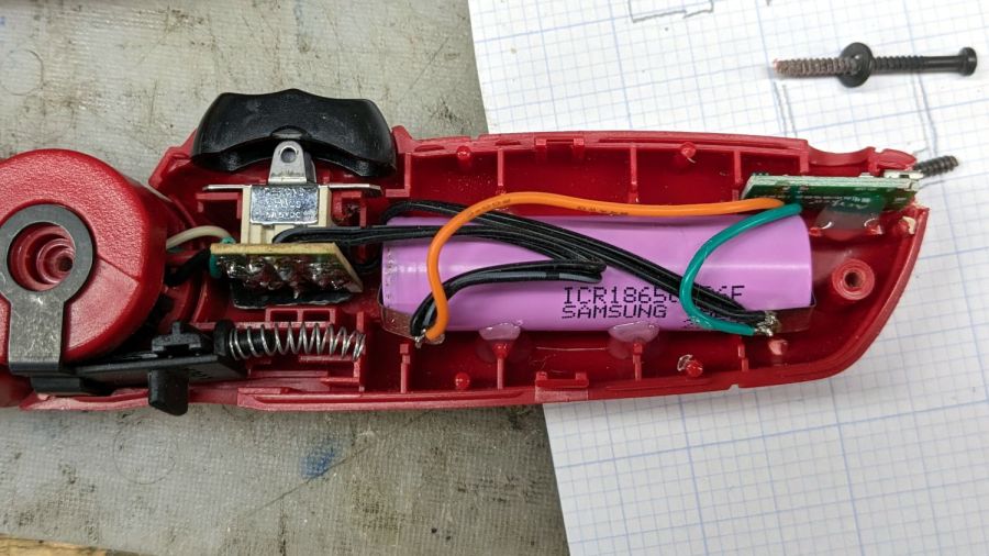
In anticipation of upcoming disassembly & reassembly tasks, I finally replaced the long-dead NiCd battery in an old Skil cordless driver with an 18650 lithium cell from the Basement Warehouse Wing:
Skil Cordless Driver – 18650 cell overview
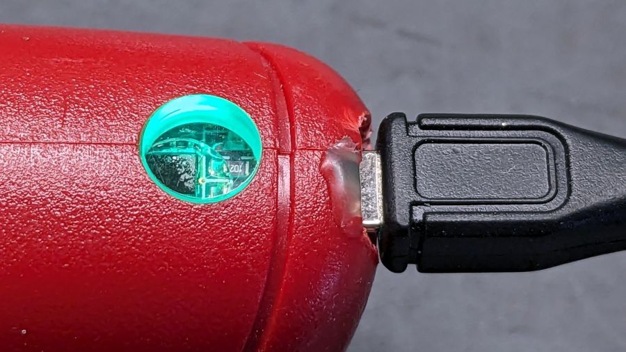
A USB charge controller sits in a slot carved into the plastic formerly supporting the NiCd battery’s charging jack:
Skil Cordless Driver – USB charger detail
Hot-melt glue holds everything in place.
The motor draws about 2 A under full load, which is a bit more than the charge controller wants to supply. I simply wired the motor (through its reversing switch) directly to the 18650 cell terminals, which is certainly not good practice, but seems reasonable given the intended use case.
A red LED shows the charger stuffing energy into the cell:
After an hour, a green glow shows the cell is fully charged:
Skil Cordless Driver – full charge
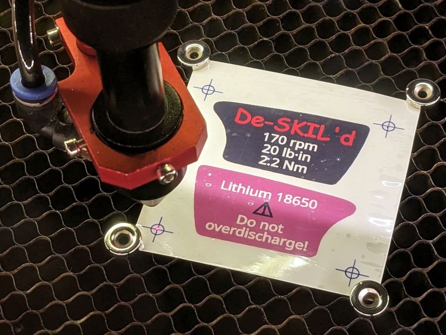
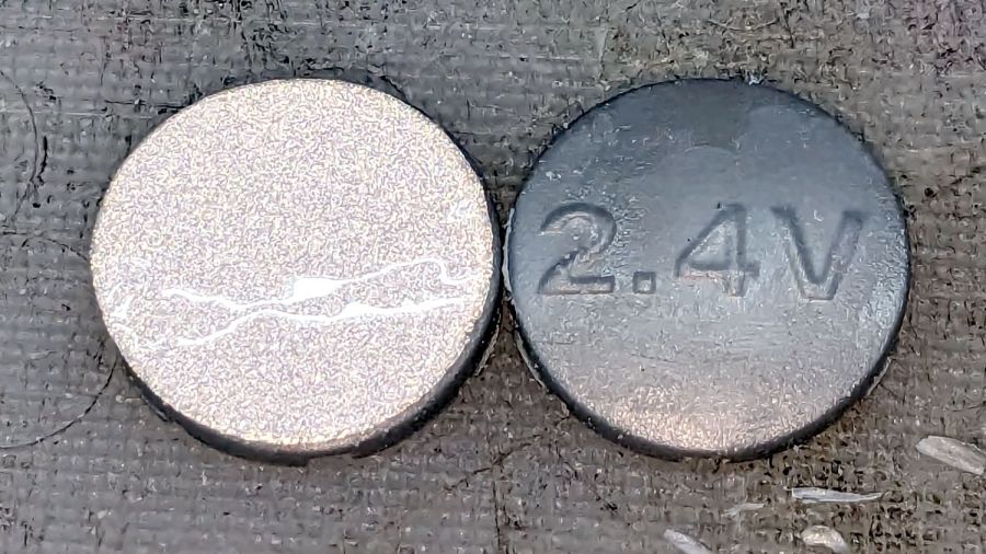
The original label proudly touted the NiCd battery’s 2.4 V, so I figured truth in packaging required a new label:
Skil Cordless Driver – new label cutting
The process:
Scan the original labels
Blow out the contrast to make binary masks
Trace into vectors with LightBurn, simplify & clean up
Add targets for Print-and-Cut
Save as SVG, import into GIMP, lay out text, print
Cut the outlines
The labels have laminating film on the top and craft adhesive on the bottom, both of which cut neatly and look pretty good:
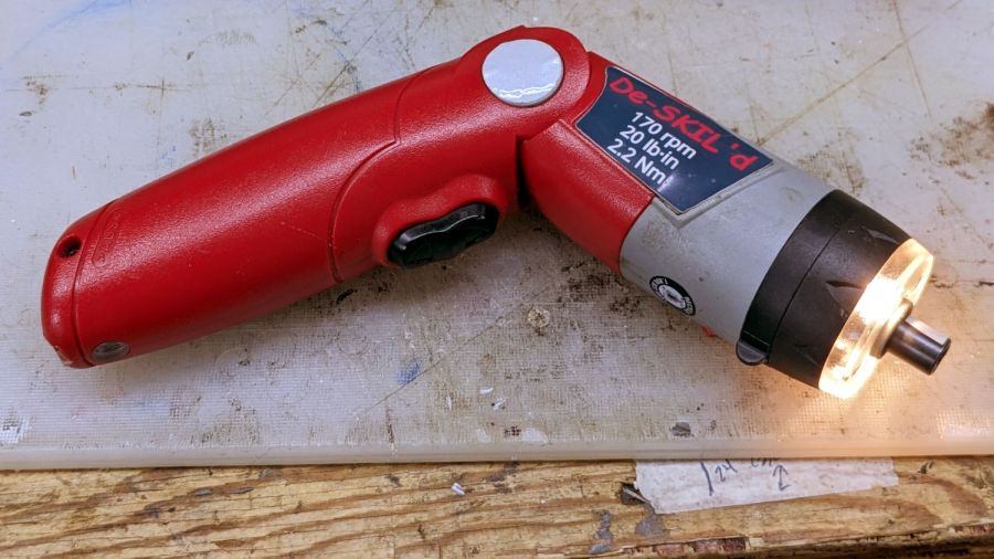
Skil Cordless Driver – lithium in action
The alert reader will note the 4+ V from a fully charged lithium cell exceeds the 2.4+ V from fully charged NiCd cells, which accounts for the very bright incandescent headlamps. I figure 4 is roughly equal to 2.4, for large values of 2.4: the driver ticks along at 170 RPM instead 140 RPM.
I measured the torque using a double-ended hex bit in a torque screwdriver, with the torque setting cranked up until the driver just barely clicked it over.
I took the liberty of filing the raised “2.4 V” off the hinge covers and adding tidy retroreflective disks:
Skil Cordless Driver – hinge cover
I briefly considered adding “3.7 V” (because “4.2 V MAX” wouldn’t fit) in laser-cut PSA vinyl, but it was getting late.
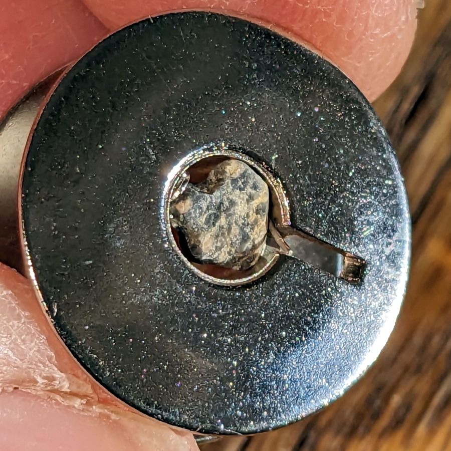
While loading bobbins for her next quilt project, Mary found another one that just wouldn’t fit on the winder:
Bobbin with polishing rock
Knocking the rock out of the bore required a pin punch and more than a gentle tap, but it eventually left without damage. The little stick in the slot looked organic, although it vanished without a trace during the operation.
I originally thought the bobbin factory’s final vibratory polisher used walnut shells, but the evidence certainly suggests ordinary gravel!
Although it’s technically sandpaper, the effect is more like lapping than sanding and the O-rings now ride on a very smooth surface.
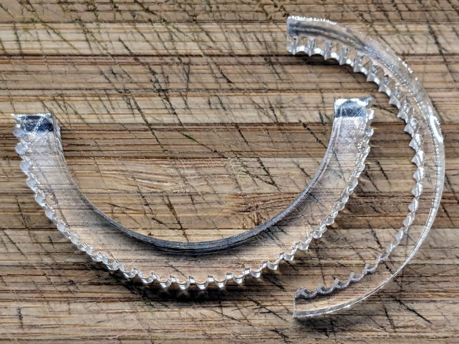
The knurled half-ring is ¼-inch = 6.3 mm acrylic with an ID precisely fitting the pillar + sandpaper:
Sink O-ring seat polishers
The one on the right has an OD matching the surface inside the spout, but it turned out to be easier using fingertips, even if that isn’t quite how one should do lapping.
The LightBurn layout shows the “knurls” are half-circles either added or subtracted from the arcs, as LightBurn’s Circular Array tool is my copilot:
O-ring Polishers – LB layout
You’ll want to measure the ID and OD of your sink faucet, as well as the thickness of your sandpaper, before making make your own.
Imagining / laying out / building those took less time than writing this up; I loves me some quick laser cutter action.
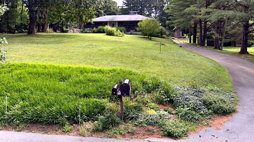
The sellers have accepted our offer on their house, so over the course of the next couple of months we’ll be moving, then selling this place. Having begun dismantling and packing the contents of the Basement Shop, Laboratory, and Warehouse, my blog-worthy activities will grind to a temporary halt.
Should you or anyone you know be interested in moving to the trendy Hudson Valley region, we have a conveniently located property with a shop-ready basement:
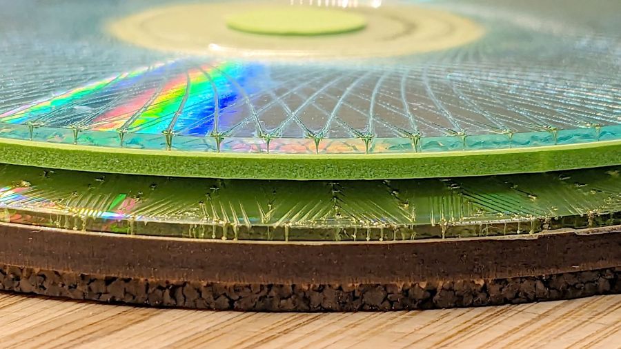
Up to this point, I’d been making coasters with a layer of cork on the bottom, held in place with wood glue (for MDF or plywood tops) or an adhesive sheet (for acrylic or glass). Doing that with a CD produced the bottom coaster:
Laser cut CDs – Foam vs MDF-cork backing – detail
Although the Mariner’s Compass pattern looks like it extends over the edge, you’re looking through the transparent polycarbonate at the deep pits burned nearly through the entire disc at the corners of the triangles where the laser head slows.
Although the MDF layer makes the coaster exceedingly stiff, it also makes it entirely too thick and much too fiddly to assemble.
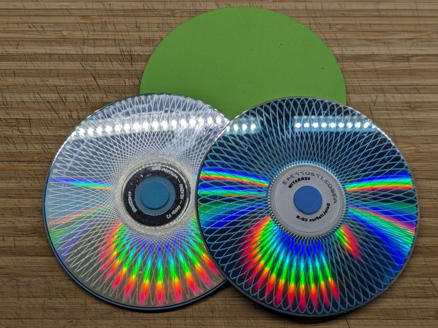
The top coaster is a Guilloche-patterned CD stuck to an EVA foam disk with an adhesive sheet. A small foam disk fills the hub hole and, not incidentally, covers the adhesive that would otherwise be exposed:
Laser cut CDs – Foam coaster backing
It’s stiffer than I expected and works well unless the mug / glass / cup has a wet bottom. Alas, the small channels cut into the CD’s surface fill up with the liquid sealing the coaster to the mug, so it sticks firmly and follows the mug upward off the table.
But they’re kinda pretty, inexpensive, and easy to assemble, which counts for something.
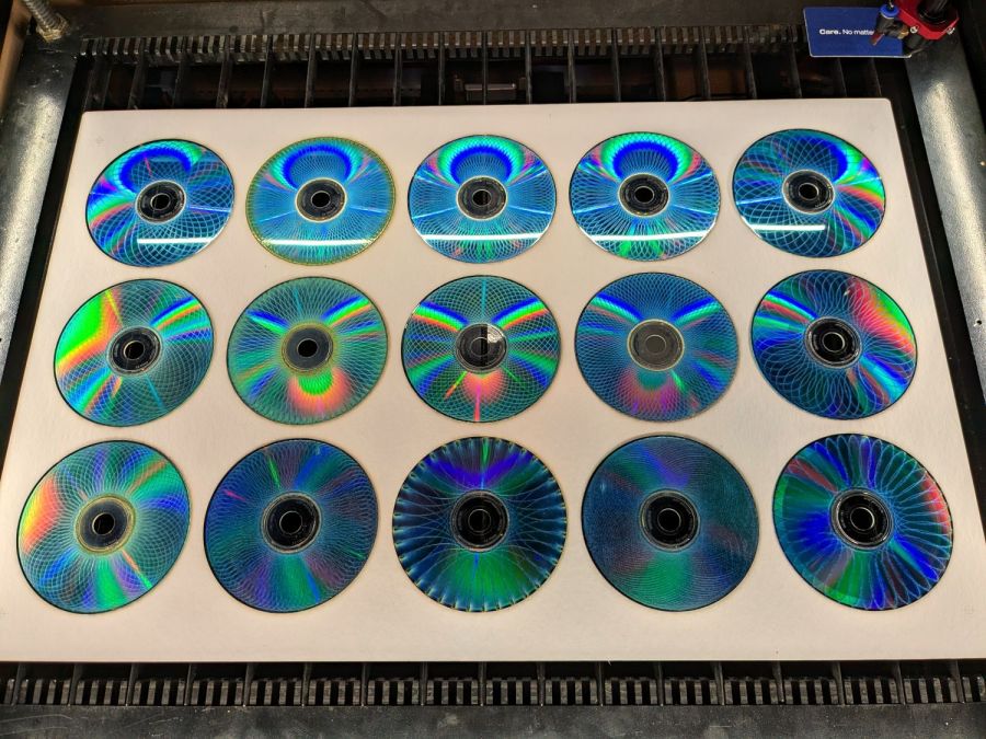
With fifteen Guilloche swirly patterns imported and snapped into the template and the template aligned to the fixture, Fire The Laser:
Laser-engraved CD fixture – legend
The whole process takes a bit under 25 minutes:
Laser-engraved CD fixture – complete
Which produces a stack of glittery proto-coasters:
Laser-engraved CD fixture – results
Although they’re all pretty-like, turning them into Real Coasters requires a cork base, MDF in the middle, wood glue, and adhesive sheets, all of which seems entirely too much like work.