The Smell of Molten Projects in the Morning

Ed Nisley's Blog: Shop notes, electronics, firmware, machinery, 3D printing, laser cuttery, and curiosities. Contents: 100% human thinking, 0% AI slop.

Category: Machine Shop

Mechanical widgetry

  • Shiny Lug Nuts: Overtightening Thereof?

    Ever notice how, when you take your car in for inspection, it always comes back with the wheel lug nuts tightened beyond the ability of mere mortals? I think it’s because they have their pneumatic impact wrenches turned up to 11, just to make sure the nuts never, ever come loose and expose them to liability.
    Broken wheel lug with attached SocketLug
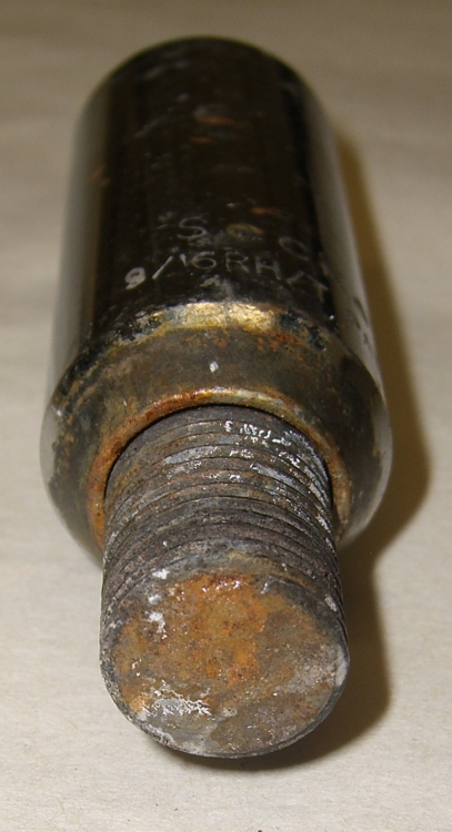
    Broken wheel lug with attached SocketLug

    Found this yesterday while walking back from the store with two gallons of milk. The shiny bit in the background is labeled SocketLug, which is evidently a trademark associated with Gorilla (but with no Web presence), and sports patent number 5797659. The stud in the front evidently snapped out of somebody’s wheel, probably flush with the surface. Gonna be trouble getting that out!

    The lug is a threaded 9/16-inch steel stud, with a root area of maybe 0.18 square inches. Let’s suppose the yield strength is 100 kpsi, so breaking that thing required 18 k pounds. The thread looks to be 18 TPI for a 1.8 degree helix angle; call it 3%. If they lubed the threads and lug (ha!), letting us assume 20% friction, then the wrench was applying 700 pounds at a 9/32″ moment arm: call it 2.5 k lb-in or 30 k lb-ft of torque. Pretty impressive, given that typical pneumatic wrenches weigh in at around 500 lb-ft of torque.

    Which says it really wasn’t the wrench doing the breaking, which should also be obvious because it was lying at the side of the road rather than on the shop floor. Even a 1000 lb-ft wrench would create only 5% of that yield load in the stud, so something else was wrong.

    That orange patch in the upper left looks like rust in a crack, with the gray area in the lower right revealing the final fault. Maybe the shop monkey (or owner?) managed to whack it while installing the tire, create a small crack that let in the usual NYS road salt, and after a season or two the stud failed after being cranked tight once again.

    There’s likely another four on that wheel: safety in numbers! Unlike those old Citroens with but a single nut securing each wheel…
  • Fairing Arcs

    In CNC machining, at least the kind I do on my Sherline CNC mill, you can’t mill around acute inside corners: a round milling bit doesn’t fit into a straight-sided angle. You must add a fairing arc that smoothly connects the two sides; the catch is that “smooth” means it’s tangent to the sides. And EMC2 is really, really fussy about smooth, to the point where you can’t just wing it with a calculator and type in the numbers.

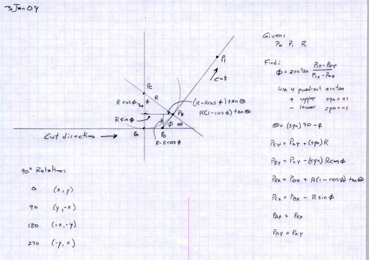
    Fairing arc doodles
    Fairing arc doodles

    There are nice analytic geometry methods for finding the intersection of two line segments, then laying in the arc that connects them, but this example weighs in at over two pages of G-Code. Mostly, what I need is an arc that connects a vertical or horizontal edge to an angled edge, so some simplification is in order.

    Herewith, the quick-and-dirty…

    The cutter enters from the left side, moving horizontally to the right, and will depart along the line toward P1, which might be the next corner of the part. The two material edges meet at P0, the vertex of the angle. The fairing arc is tangent to the two edges at PA and PB, centered at PC, and with a radius R.

    We know the coordinates of P0 and P1 and the arc radius. That radius must be larger than the cutter radius, as you can’t tuck a fat cutter into a narrow corner.

    The problem is to find PA, PB, and PC, so that we can write the G-code commands that travel along the sides & the arc.

    The first step is finding Φ (Phi), the angle between the outgoing edge and the X axis:

    Φ = arctan Δy/Δx = arctan (P1y – P0y) / (P1x – P0x)

    I’m pretty sure if you use a 4-quadrant arctan, as shown in the doodle, all the angles will work out perfectly on either side of the axis, but it’s easy enough to fake the signs to get the right answer in any specific case. If you wanted a general solution, you’d have a two-page subroutine, right?

    You’ll need the complement of that angle, hereinafter known as Theta:

    Θ = 90 – Φ

    Find the distances between various points using good old trig and right triangles:

    • CBx = R · sin Φ
    • CBy = R · cos Φ
    • P0PBy = R · (1 – cos Φ)
    • P0PBx = P0PBy · tan Θ

    Then the coordinates fall out thusly:

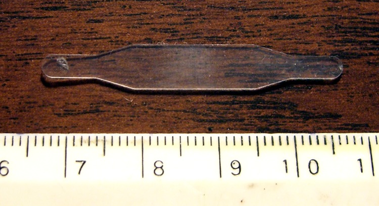
    Plastic Spring with Faired Corners
    Plastic Spring with Faired Corners
    • PCy = P0y + R
    • PBy = PCy – CBy
    • PBx = P0x + P0PBx
    • PCx = PBx – CBx
    • PAx = PCx
    • PAy = P0y

    Remember, you do not figure all this out with your calculator and plug the numbers into the G-code, not if you have any sense. If you have just a few corners, write the commands directly, otherwise gimmick up a little subroutine. Earlier versions of EMC2 used numbered parameters (#100), but now that you can have named parameters (#<_Fairing_Radius>), what’s holding you back?

    For example:

    #<_CBy>	= [#<_Fairing_Radius> * COS [#<_Phi>]]	(Y distance PC to PB)

    If your edge doesn’t come in from the left, then manual 90 degree rotations apply.

    0: (x,y) -> (x,y)
    90: (x,y) -> (y,-x)
    180: (x,y) -> (-x,-y)
    270: (x,y) -> (-y,x)

    If you’re using a CAD program to lay out your parts, all this is largely irrelevant. I hammer out the G-code for the simple 2-1/2-D parts I make by hand, so rounding off a few corners comes in handy.

    Because the lines & arc define the material edge contour, you can mill on either side of it and use cutter radius compensation to make the answer come out right. Works like a champ!

    For what it’s worth, the arc is tangent at PA and PB, making the line from PC to the corner (a.k.a. vertex) P0 the bisector of angle Φ. That’s not directly useful here, but keep it in mind when you solve similar problems.

    Update: As of mid-January, the newest trunk version of EMC2 can automagically insert fillets when cutter comp is turned on. That’ll be in the stable version in a while, after which I’ll need this math only for decorative fillets. That’s fine with me!

  • Fluorescent Shop Lights, Early Failures Thereof

    A decade ago I installed a few dozen two-tube fluorescent fixtures (a.k.a. “shop lights”) throughout the basement. Visitors always say something like “Wow, I can actually see what I’m doing!” That was the whole point, of course.

    Being that sort of bear, I write the date on one end of a fluorescent tube when I replace it. Tubes seem to last 3-5 years, which is short compared to the 20k power-on hours touted on the carton: 5 years * 300 days/yr * 6 hr/day = 9 k hours. That’s an overestimate, as I don’t spend all my time crouched in my basement laboratory, honest.

    It turns out that there’s also a spec for the number of lamp turn-ons (“starts”) hidden deep in the lamp datasheets. For example, if you manage to browse the current Lamp and Ballast catalog at http://www.sylvania.com/ProductCatalogs/, you’ll find that a 20k hour rated life comes at “3 hr/start”, which works out to a mere 6.7k starts over the expected life.

    More starts = shorter life.

    I tend to turn the lights off if I think I’ll be upstairs for a few hours, which happens a lot during the winter.  My back of the envelope says that the tubes fail right around the expected value: 5 years * 300 days/yr * 4 starts/day = 6 k starts.

    Lately I’ve had a rash of early lamp failures and it seems the fixtures are failing after a decade; nothing lasts any more. I’m now installing electronic-ballast fixtures that fire right up in the winter and don’t have that annoying subliminal flicker. At a cost of $20 each, I’m not replacing all of them at once, I assure you.

    The only real problem with fluorescent lamps is that they make white people look dead. I managed to buy a contractor pack of warm-white tubes at the local Lowe’s, but they’re hard to find around here. Go for the lowest color temperature bulbs you can find.

  • Sunglass Repair

    Making the fixture
    Making the fixture

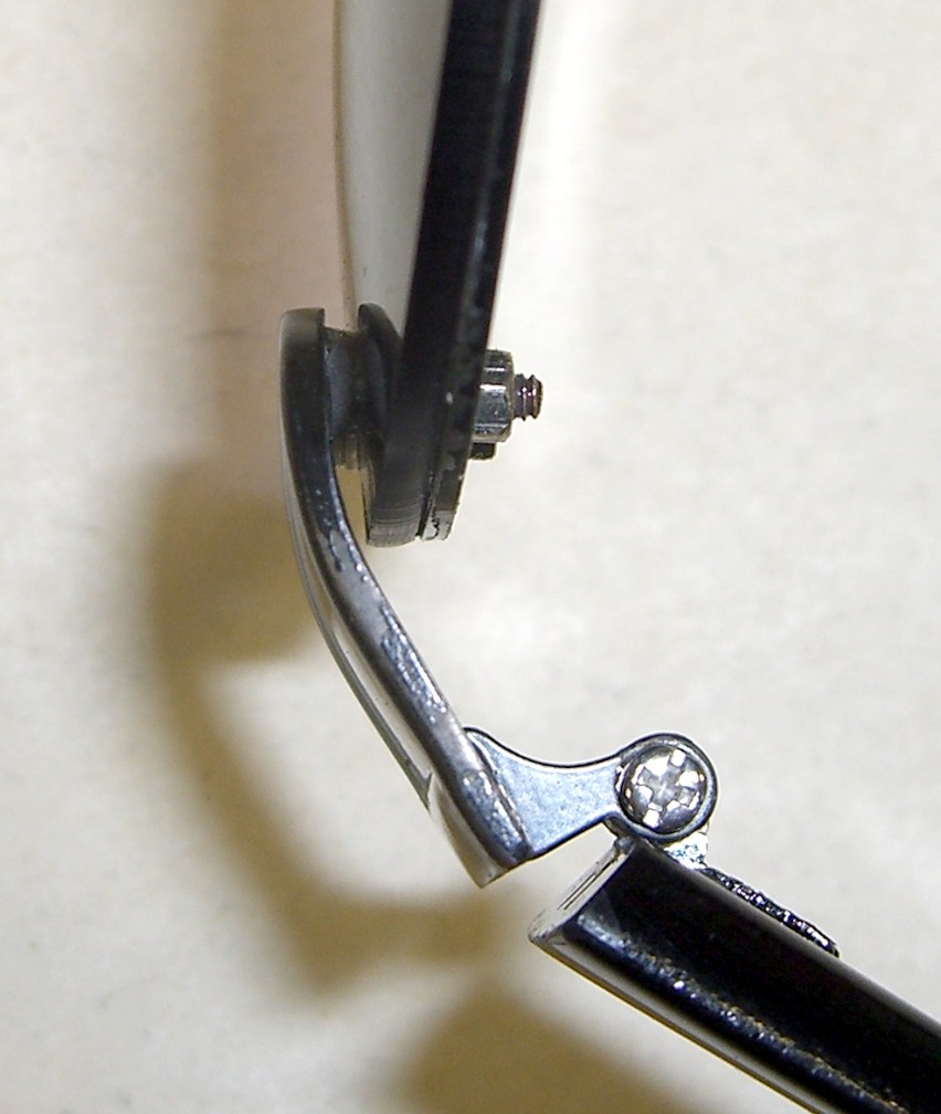
    One of the screws on Mary’s sunglasses came apart. Wonder of wonders, the nut fell off in the kitchen, made a click when it hit the floor, and we managed to collect all the pieces.

    The temples attach to the lens frame with two tiny screws apiece. The screw heads are slightly embedded in the temples, but you can see why this didn’t work nearly as well in practice as it did in the design studio.

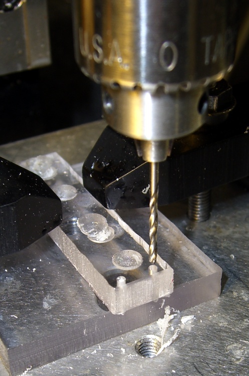
    The trick is to align the screw properly so it fits through the lens and frame after the adhesive sets up. The holes are 6 mm on center and more-or-less 55 mils in diameter (obviously, they’re metric screws, but this is the US and we do the best we can with antique units).

    Clamping and curing
    Clamping and curing

    That’s what CNC is all about: making it trivial to poke holes exactly 6 mm apart on center. I drilled two holes in some scrap acrylic sheet using Manual mode on my Sherline / EMC2 mill:

    g83 z-7 r1 q0.5 f100
    g0 x6
    g83 z-7 r1 q0.5 f100
    g0 z100

    I have it set to start up in metric units, which still seems to be legal here.

    cimg2858-sunglass-repair-success
    Success!

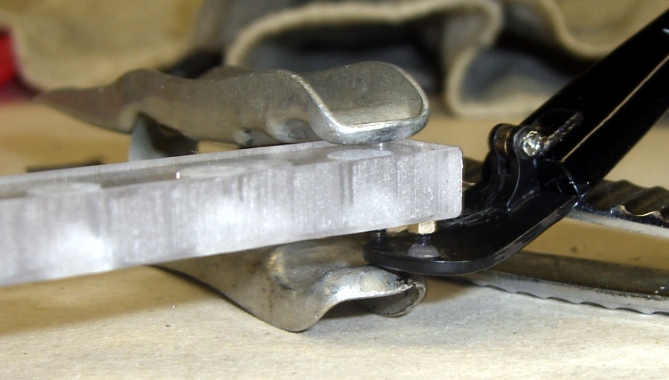
    Add a teeny dab of JB Weld, hold everything together overnight with a clothespin, and it’s all good in the morning.

    The trick is to check the leftover epoxy first to see if it’s fully cured before you move the actual piece.

    Memo to self: epoxy takes forever to cure at 55 F.

    Update: Pretty much as expected, that little dot of epoxy didn’t hold nearly as well as the original brazing. I tried a somewhat larger dot, but Mary was unhappy with the glasses anyway and we finally tossed ’em out.

    Of course I salvaged the screws & nuts & suchlike: you gotta have stuff!

  • Geek Scratch Paper

    Grid scratch paper pad
    Grid scratch paper pad

    Everybody needs doodle paper, but geeks need graph paper. What to do?

    Go to http://incompetech.com/graphpaper/ and set up a half-page grid with 5×8 1-inch divisions, 0.5-inch mid divisions, and 0.1-inch minor divisions (I think 1 / 0.6 / 0.3 pt line widths look nice). The obvious metric divisions are a bit too fine for my taste, but 2 cm – 1 cm – 2 mm might work.

    Fetch the PDF, load it into The GIMP at 300 dpi, expand the canvas to a full-page sheet (8.5×11 inches), duplicate the grid so you have two on one sheet, save it as a PNG for later use.

    If you don’t have a full-bleed printer, pick a full-page size that’ll print within whatever margins your printer enforces. You really want those one-inch grids to remain one inch, right?

    Print a few dozen copies, whack ’em in half, and bind ’em on the long edge. Add a thin cardboard backing sheet (Mr Breakfast Cereal Box, meet Mr Paper Cutter) so the bottom sheet stays neat.

    I have an old IBICO (since absorbed by GBC) plastic comb binding machine, but it’s easy enough to line the sheets up and coat the edge with white paper glue, rubber cement, or, for the true geek, liquid electrical tape.

    Pre-position pads wherever you’re ordinarily at a loss for scratch paper: neat doodles!

    PS: Put some money in his tip jar when you use his graph paper. It’s a nice gesture.

    [Update: Inexplicably, I didn’t have a picture of a pad. Here you go… low res, but you get the general idea. Great for off-the-cuff graphing, too.]

  • Small Sherline Clamps

    Made six hold-down clamps for the Sherline mill, inspired by this much fancier project:

    http://www.sherline.com/tip5.htm

    Adapted Bookshelf Extrusion and Screws
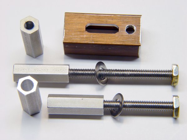
    Adapted Bookshelf Extrusion and Screws

    He used steel clamps, brazed on little brass snippets, and used brass hex rod for the nuts. I hate machining steel, particularly in teeny pieces, and didn’t have any brass hex stock that small: improvisation was in order!

    So I sawed up an old aluminum bookshelf rail, CNC-ed the slot (more practice writing G-code), sawed the heads off some stainless 10-32 screws, and produced something that might work just as well.

    My stash has a lifetime supply of 10-24 brass nuts, so I jammed them on the end of the 10-32 screws in the back to act as pads against the mill table top. No finesse there…

    The T-slots aren’t quite deep enough for the nuts, though, so I milled 15 thou off each side of another six nuts and discovered, once again, that you can’t take an arbitrarily thin cut unless you have an arbitrarily sharp cutter… which, of course, I don’t. Made a plastic spacer to hold the nuts just high enough to nibble off the excess and just low enough to grip ’em in the mill vise. Did the whole thing without leaving embarrassing scars on the vise or ruining the cutter, much to my delight.

    Tapped the slenderized nuts 10-32 (how crude!) and applied green Loctite to the three goobered threads to lock the screws in place. The flats just clear the T-slots and the thickness is just barely OK, so I declared success.

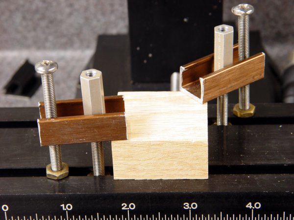
    Clamps In Action
    Clamps In Action

    The Good Idea in the original project lies in the long hex nuts. They’re drilled out about 3/4 of their length to clear the 10-32 screws, so you can just drop them on and spin a few times rather than tediously twisting them all the way down. My stash yielded some 2-inch aluminum standoffs tapped for 4-40 screws on each end; cut ’em in half, drilled out the raw end, drilled-and-tapped the existing holes to 10-32, and there they were.

    And, best of all, my fingers will smell like tapping lube for the rest of the month… ah, shop time!

    Update: You can cut a nice taper on the nose if you don’t like the relentless square aspect of those things or need a bit more clearance. They’re peeking into the sides of the bottom picture there, holding the sacrificial plate in place.

  • Park MTB-7 Rescue Tool Repair

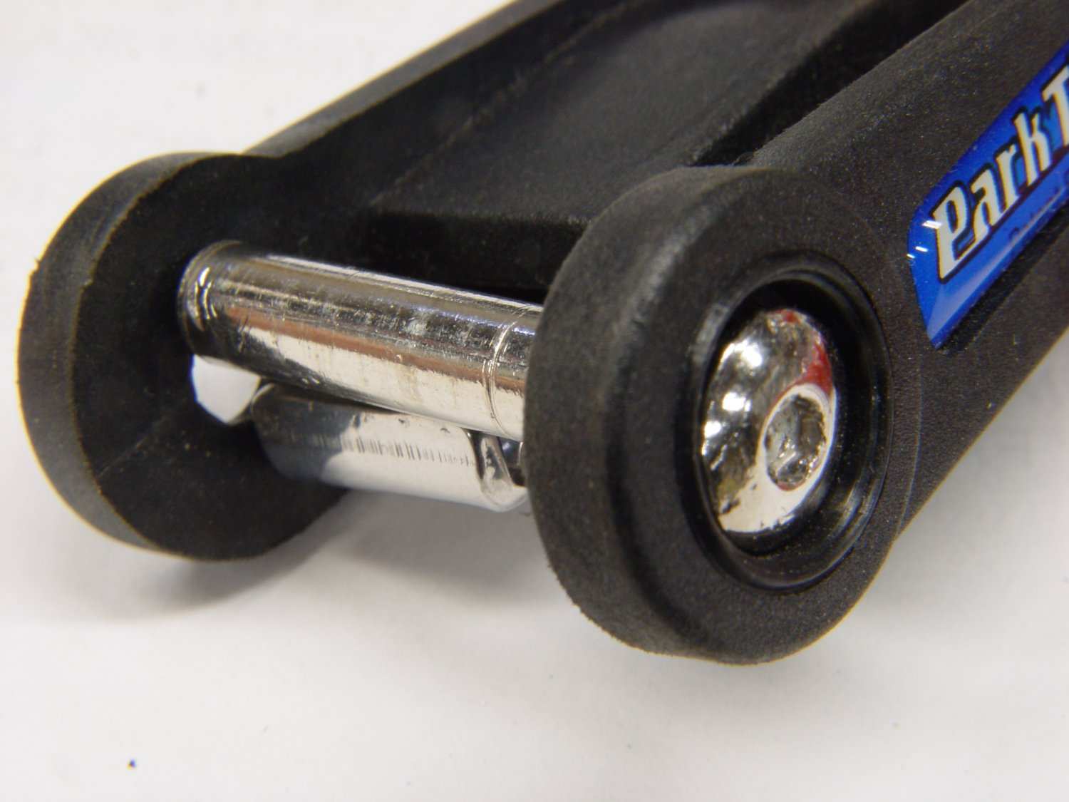
    Too-short Stud
    Too-short Stud
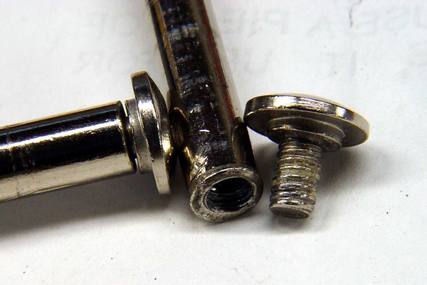
    Goobered Screw Threads
    Goobered Screw Threads

    Once upon a time I deployed the 6 mm hex wrench on my trusty Park MTB-7 Rescue Tool, applied some torque to a handebar stem bolt, and crunch something broke inside the tool.

    [Update: Fixed a dead link; Park evidently reshuffled their website.]

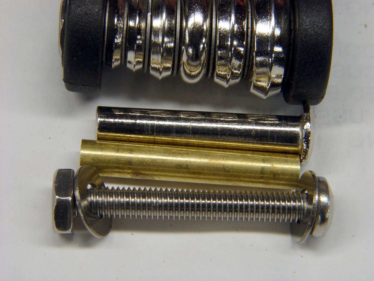
    The essential problem is that the studs holding the tools in place are too short: they don’t seat fully into the plastic housing at the far end, because they’re 2 mm too short. The photo showing the stud at an angle gives an idea of the situation I saw when I took the tool apart.

    The crunching sound I heard was the screw tearing out as the stud shifted in the housing. The studs seem to be swaged into shape in one operation, but without quite enough material: the threaded end isn’t flat and the internal threads are crap. The photo showing the studs and screws can’t really show how off-center and feeble the internal threads really are, but you can see the junk lodged in the external screw’s threads where it tore out. Note the poor fit between the other stud’s end and its screw: it’s firmly seated against the stud, so that’s how far off square the end is!

    Better Screw and Sleeve
    Better Screw and Sleeve

    The fix was easy enough. I cut some brass tubing to the proper length, trimmed stainless-steel 10-32 screws to fit, and put everything together with red Loctite. The photo showing the all the parts indicates how much longer my sleeves are than the original studs: basically, that’s the thickness of the plastic housing on one side.

    But, sheesh, you’d expect a Park tool to be better than that. I sent ’em a note with pictures and maybe they’ll smack the factor who shorted ’em on the Quality bullet item upside the head.

    I got to spend some time playing with my toys, so it wasn’t a dead loss.