
OK, I had to do it. The Alpha-Geek Clock WWVB receiver circuitry, such as it is, now resides in a nice Pactec enclosure, with a bright red LED.
All time, all the time, and nothing but the time.
I should put it up on etsy.com for fifty bucks…
The Smell of Molten Projects in the Morning
Ed Nisley's Blog: Shop notes, electronics, firmware, machinery, 3D printing, laser cuttery, and curiosities. Contents: 100% human thinking, 0% AI slop.
Mechanical widgetry
OK, I had to do it. The Alpha-Geek Clock WWVB receiver circuitry, such as it is, now resides in a nice Pactec enclosure, with a bright red LED.
All time, all the time, and nothing but the time.
I should put it up on etsy.com for fifty bucks…

We took down the deer netting around the garden yesterday, which involves pulling a zillion staples out of the wood posts. I put some salvaged hard-drive head motor magnets to good use: one magnet inside my jacket sleeve to hold the other magnet in place, then just drop staples near them.
Shazam… no staples in the ground!
You can actually buy such things, with cute Velcro straps and all, but why? You’ve been saving those magnets for years: put ’em to use!
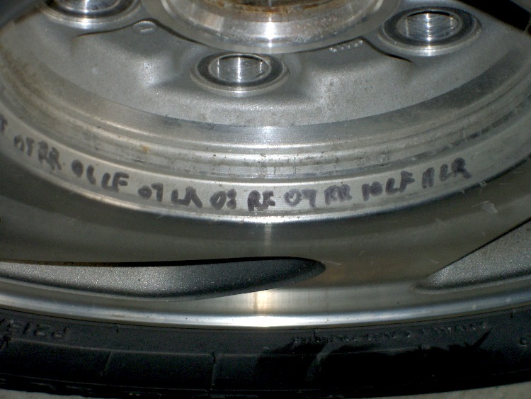
A discussion there reminded me to mention a good habit taught by my buddy Eks: when you must look something up, write the information where you’ll see it the next time you need it.
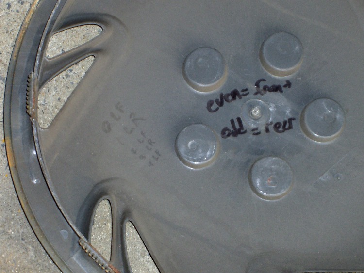
So, for example, each of the van wheels sports its own tire-rotation schedule inside the cover. When it’s time to swap tires in early spring and late autumn, I pry the cover off, read where the tire should go, and do the deed. I write ’em down four or five years at a time, so there’s not much thinking involved.
The engine compartment has all the most-often-used wrench sizes and capacities.
I write the oil change & inspection info in the maintenance schedule booklet that came with the van, although after a decade that’s pretty much full up.
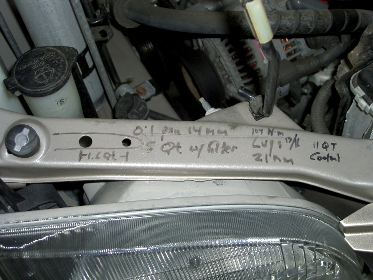
Sharpies FTW!

Just chopped up a 5-lb lump of Provolone into 2-oz chunks for pizza, which brings this simple shop project to mind: a cheese garrotte.
It’s about a foot of 0.011-inch (call it 0.25 mm) stainless steel wire with the ends wrapped around some aluminum rod, neatly tied off with heatshrink tubing.
Usage is about what you’d expect: it cuts cheese like nothing else on earth. The only trick is maintaining a straight line, which is easier (for me, at least) when I cut vertically downward.
It’s difficult to cut all the way to the bottom and that wire is rough on the fingertips, so I tend to flip the cheese over and pull sideways for the last inch or two. Maybe not a perfect cut, but good enough.

Construction nuance: loop the wire around the handle once or twice, pass it through the hole, then do another loop before twisting the end. If you run the wire directly through the hole, it’ll break on the far-side sharp edge after a while, even when you countersink the hole.
I put a shallow groove around the handle, but that’s likely not needed. You can certainly get fancier with the handles if you like. This one is dishwasher safe, which makes up for a lot.
You really, really need heatshrink tubing over the bare wire ends, as the tip of a 11-mil stainless wire is indistinguishable from a needle.
For about the last week I’ve noticed a soft clicking-buzzing sound somewhere near the dashboard / center console of our 2000 Toyota Sienna. I tried some on-the-fly isolation, but it wasn’t related to motion, engine on/off, CD or tape player, fan, or anything else. Finally Mary noticed it, too, and we spent half an hour in the garage yanking fuses and wiggling things until we tracked it down to below the passenger seat.
Now, in the good old days, that was empty space, but in the Sienna it’s where the rear-area heater lives. Shoving the seat forward to the stop exposed the heater and, sure enough, it’s buzzing and clicking. Intermittently, somewhat randomly, but very steadily.

With that as a hint, I twisted the rear-area temperature control (on the headliner behind the driver seat) and shazam the noise stopped. The control has detents and when moving the control to each detent the heater makes a faint buzzing. I suspect the control adjusts a valve that regulates engine coolant flow inside the heater.
It’s not obvious whether the control is a pure-digital rotary encoder or a potentiometer, so I decided to investigate: it’s already sorta busted, what’s to lose? The bezel comes off by prying its door-side edge outward. The white plastic frame has two screws into the metal structure under the roof. The two electrical connectors are, of course, the positive-latching kind that you pull the little tab until you break your fingernail and then realize that you should push it instead.

Taking the control apart reveals that it’s a potentiometer with some switching contacts. The two bifurcated spring-finger contacts on the black plastic disk short the resistive element to the inner metallic track.

The metal contacts appeared slightly grody, but with no major corrosion. The resistive track looked just fine.
The offending control position would be to the left side of the element as shown in the pictures here: there’s nothing obviously wrong at that spot. I think the maximum-heat position is off the resistive element entirely, resting on the far left end of the metal traces, but the control wasn’t quite set to that spot. Perhaps the problem was that the contacts became intermittent at the exact edge of the element.
I smoothed the collection of anti-oxidation grease over the tracks, covered the contacts with their own blobs, put everything back together, and it works fine.
We tend to put the control at A/C during the summer and at maximum heat during the winter. I suppose the poor thing got frustrated after we moved it a month or so ago…
The money saved with this repair might just pay to have the Toyota dealer replace the spark plugs. The shop manual says that task starts by removing the windshield bezel and all the stuff above the engine intake manifold; the job costs upwards of 300 bucks. I can barely see the rear plugs with a looong inspection mirror angled just so while lying on the floor under the van, so it’s truly a nontrivial operation.
I [delete] all over their [censored]…

For reasons that shouldn’t require the least bit of explanation by now, I had to dismantle(*) an old 2-D-cell Maglite. The operative word here is old, because you can find plenty of instructions & pix telling you how to dismantle the newer (post-2001, evidently), cheapnified Maglites. Mine dates back to the early days.
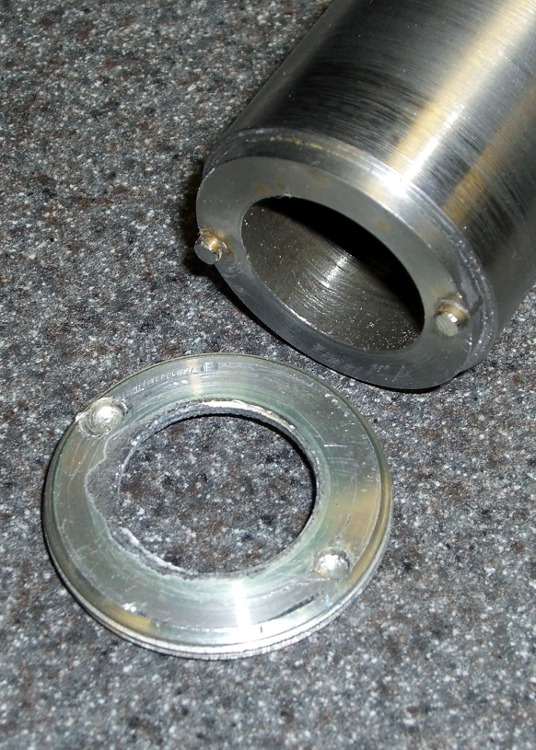
Unlike new(er) Maglites, the switch assembly in this one comes out through the front. An aluminum retaining nut holds it in place, as shown in the first picture. You’ll find directions telling you to unscrew the nut by jamming a pair of needle-nose pliers into the holes, but that’s not how it’s done.
The job calls for a pin wrench!
Measuring the dimensions is no BFD after you’ve got the damned thing apart, but I didn’t have that luxury. Given this was an American product from back in the Olde Days, I assumed everything was denominated in inches, which turned out to be close enough.

The “Max” dimensions at the bottom are the actual ID measurements from the housing after disassembly, using telescoping gages. I made the wrench to the dimensions on the line just above and they worked fine.
Believe it or not, I found a steel cylinder in my scrap heap that was just exactly what I needed, right down to the 7/8″ bore in the middle. Not only that, it was free-machining steel. Whew!
The inner bore must clear the brass screw head sticking out of the lamp tower in the middle (which rides in a slot as part of the sliding focus mechanism). Once you’ve extricated the switch assembly, you remove that screw with a 2 mm (so much for hard inch dimensions) hex key. If you’re desperate, you can probably worry the screw out by goobering it with the aforementioned needle-nose pliers; it has an ordinary right-hand thread.
I turned the cylinder down in the lathe, then drilled the pin holes. That’s a mistake: the outside edge of the pins is exactly even with the OD of the wrench nose. If you do this, clean up the stock OD & face the ends to get a nice cylinder, drill the pin holes, then turn down the barrel clearance and nose. It need not be perfectly concentric, so stop worrying.

I did the drilling using manual CNC on the Sherline mill, mostly because that’s the only way I could poke the holes in the right spots. The mill doesn’t have a lot of vertical headroom, so I clamped the wrench directly to the table and touched off the X and Y axes to put the origin in the center.
I got it all clamped down, removed the right-hand clamp to touch off on the +X side, then re-clamped it.

Center drill to fix the hole location. Drill 1/8″ about 0.250 deep: 3000 rpm, 10 ipm feed, use a little cutting lube. Do those both in sequence at each hole.
I sliced two overly long stubs from some 1/8″ drill rod with a Dremel cutoff wheel, dabbed JB Weld in the holes, and poked them in. The next morning I sliced them down to about the right length, cleaned up the ends with a file, broke the edges, and the wrench was good to go. The pin length in the drawing was what I’d have used if I could have measured the holes before taking it apart.
The pins were actually on the long side of 60 mils, just an itsy too much to keep the wrench flat on the nut. The next picture shows some gouging on one of the holes, due entirely to not engaging the wrench quite enough at first.

I thought about putting flats on the wrench, but simply grabbed it in the bench vise, swallowed it with the flashlight, engaged pins with holes, leaned into the wrench, and unscrewed the ring. It took a lot more force to get those threads turning than I expected, but the ring eventually spun out easily. Right-hand threads, of course; obvious after the fact.
Before you can remove the switch assembly, you must pry off the rubber switch cover, stick that 2 mm hex wrench down the hole thus revealed, and unscrew the setscrew ‘way down inside there. That backs the setscrew out of a recess in the housing that makes electrical contact with the negative end of the bottom D cell. Do that before you remove the ring, lest you forget.

Surprisingly, the blue plastic switch housing seems to be slightly soluble in potassium hydroxide. Who knew?
With the switch assembly out, you (well, I) can proceed to beat the corroded cells out by chucking the housing in the lathe (it exactly seats on the three-jaw chuck’s front face!) and ramming a fat dowel up its snout with a two-pound hammer.
Yeah, genuine Ray-O-Vac Maximum D cells: they all leak if you leave ’em in there long enough. This flashlight worked fine, right up to the point where I checked inside to see how long the cells had been in there. Oops.
I’m thinking of rebuilding it with some killer LED clusters up front; scrap the reflector, rework the switch assembly. Certainly that’d have better heatsinking than those absurd 3-watt LED bulb-like thingies.
(*) Yes, Maglite has a lifetime replacement warranty that even covers death due to battery corrosion. Now, I ask you, what’s the fun in that?
Here’s an example of the dimensional accuracy you can get from toner-transfer PCBs in real life.
I drill the holes with a CNC-ed Sherline mill, so they’re pretty much spot on. Drilling the holes by hand simply isn’t practical: there’s no way to get both global alignment and local accuracy.
The toner transfer sheet, printed on a laser printer, gets aligned to the existing holes atop a light table. The paper stretches & shrinks and moves around while printing, but I can generally average out the errors so that the 24-mil holes (the smallest I generally use) across the board have no more than a few mils of error: the pads don’t show more than that inside the drilled holes. In the picture below, you can see a dark rim around the corner alignment hole that looks worse than it really is due to the perspective.
I put the toner transfer sheet on the light table, toner-side up, lay the PCB atop the paper, and adjust for best overall alignment. I then tape them together along one edge with strips of laser-printer address labels: guaranteed to hold up to high temperatures, which is more than you can say for most tapes.

Here’s the board after etching both sides, with the black toner and green sealant film still in place. The toner & film are slightly smeared from the solvent I used to clean off the other side before etching it. The brownish dabs on the green areas come from a brown Sharpie that works fine as a touch-up etching resist.

The narrowest traces are 16 mils, most of the others are 32 mils, and the fat ones down the middle of the chip are 40 mils. Click on the images for bigger versions; you’ll get some JPG compression artifacts, but the resolution is good enough to see what’s going on.
Here’s the same area with the toner removed and a touch of silver plating applied to make it pretty and more easily solderable. The colors aren’t particularly reliable; in real life, it’s a lot more silvery.

Fairly obviously, the alignment isn’t nearly as good as you’d expect from the initial taping. In round numbers, the pads to the left side seem offset by about the diameter of the holes; call it 25 mils. The holes in the DIP pads are off by perhaps 10 mils.
The bottom surface looks pretty much the same, with similar alignment issues.

The misalignments are not uniform, as you’d expect if the toner transfer sheet moved across the board during fusing. The sheet deforms during the fusing process in a completely unpredictable way, despite my trying all of the usual tricks:
It’s fair to say you (well, I) can get within 25 mils of a board hole for sure, less than that most of the time, and be spot on over much of the board. I use large pads and vias for anything I have control over, as witness the pads surrounding the DIP, and avoid very fine features near holes.
Anyhow, it’s good enough for what I do, but you shouldn’t get your hopes up that toner-transfer circuit boards come anywhere close to commercial quality. If you’re doing a lot of pure surface-mount work, it’ll probably be good enough because there’s no need for global alignment to holes in the underlying board. Obviously, the smaller the board, the better off you’ll be.
I etched this board by rubbing ferric chloride on it with a sponge (wearing forearm-length rubber gloves and a shop apron!), renewing the solution as it turned black and gooey. Works like a charm, gives good control of the process, doesn’t erode the Sharpie masking, doesn’t over-etch the traces (much, anyway), and uses less etchant than soaking the board in a bath.
I have other posts describing the process in more detail. Search for PCB, toner-transfer, and other keywords to unearth those entries.
