Ed Nisley's Blog: Shop notes, electronics, firmware, machinery, 3D printing, laser cuttery, and curiosities. Contents: 100% human thinking, 0% AI slop.
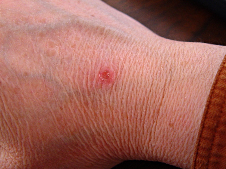
This should be obvious, but don’t reach across the build platform of your Thing-O-Matic with the extruder at 215 °C: you might bump the nozzle with the back of your hand.
Scorch mark from TOM nozzle
It never really hurt, but the nozzle tip made a nasty punch mark in the middle of a disk of scorched skin.
This is a better view of the alignment process that I endure once a year when I haul my Sherline mill back from Cabin Fever. The whole thing depends on a laser level that I’ve gutted and clamped to the floor joists over the mill, as described there.
The first step uses a plumb bob to position the hacked laser level lens directly over the Sherline’s spindle bore. I’ve shimmed the countertop under the mill to be pretty much level, so a vertical line from the bore determines where the lens must be.
Then I fiddle around to get the beam directly in the middle of the spindle bore, using a slip of paper to figure out where it’s going. The top picture shows the result.
Having done this a few times, the laser level starts out pretty much aligned, but the first setup required quite a bit of back-and-forth twiddling of the screws.
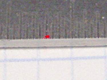
Then I put a mirror flat on the Sherline’s table / tooling plate to reflect the beam back up the spindle. More fiddling around gets the reflected spot pretty close to the outgoing beam; this picture shows the spot just off-center near the top (actually, toward the base of the laser level’s frame) of the aperture.
Reflected spot near laser aperture
When the outgoing and reflected beams converge, then I put the bushing (without the polarizing filter) in the top of the spindle bore to reduce the beam size and fine-tune the positions & angles.
Surprisingly, it stays in position quite solidly. I do twiddle it every now & again, but as long as the beam gets through the bore it’s close enough.
A display across the aisle from the CNC Ghetto at Cabin Fever featured a nice Laser Center Edge Finder with their new polarizing attachment. I played with it for a while and decided that, although my crude lashup gave similar results, I just had to have a polarizing filter, too.
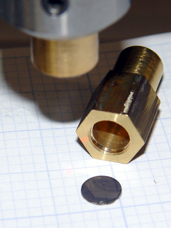
I’d already made a bushing to fit the top of the spindle bore with a small aperture that aids in lining up the laser, so I just added a small recess for a disk of polarizing film. I have, for reasons that should not require any explanation by now, a lifetime supply of polarizing film…
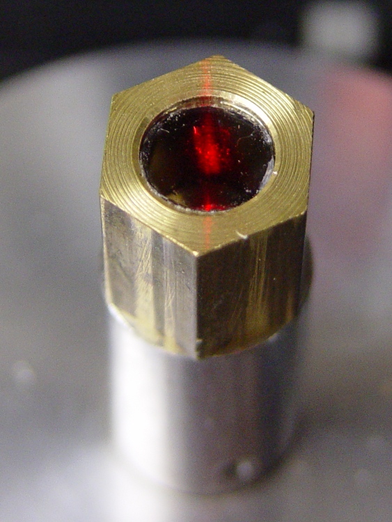
Anyhow, the new polarizing filter sits neatly atop the spindle. The main laser beam lights up the middle of the filter, with junk light spilling on the bushing to the front and rear.
Polarizing film in upper bushing
Getting a good photograph of the spot size poses some problems, but here goes. This is the original, un-attenuated spot on a scale with 0.5 mm divisions: in round numbers, it’s half a millimeter across.
Normal laser spot size
Cross-polarizing the beam produces this attenuated spot on the same scale: it’s 0.25 mm in diameter, maybe a bit less. Call it 10 mils.
Attenuated laser spot size
Obviously, what you’re seeing are overexposed more-or-less Gaussian spots, so their diameters aren’t fixed numbers. But at this level, the inaccuracies of my Orc Engineering lens mount are comparable to the spot size, so reducing the spot any further isn’t going to improve the overall positioning accuracy.
It’s worth noting that the spot size isn’t the same as the positioning accuracy: you can visually align a workpiece mark to less than 1/4 the spot diameter. Claiming 1/10 the diameter would be more brag than fact, at least for me, but somewhere around 2 mils is close. That’s good enough for most of what I do.
Here’s how you measure the height of the extruder head over the build platform to calibrate the Z-axis travel: a taper gauge.
Home the Z stage, zero the readout, move the stage downward by known increments until it’s less than 4 mm above the platform, then slide a taper gauge under the nozzle until it touches. Read off the actual nozzle height above the platform, add that to the distance you moved the nozzle from its home position, and you have the total Z axis travel.
For example, right now my TOM Z axis travel is 115.3 mm. Plug that into the homing routine in start.gcode and you’ve got perfect nozzle height control.
Here’s a Starrett No. 270 taper gauge showing the nozzle 1.65 mm above the platform. One might quibble with the last digit, given the bit of snot hanging from the nozzle, but it’s pretty close.
Taper gauge below nozzle
Nice things:
You won’t accidentally ram the nozzle into the platform
The gauge flattens out small belt waves
You don’t squint at tiny vertical differences
Bad things:
Assumes a flat platform, which really should be true anyway
Seriously spendy (see below)
The gauge has inch divisions (0.001 in) on one side and metric (0.05 mm) on the other. I’ve put plenty of hours on the metric side in recent weeks.
Starrett 270 Taper Gauge – inch side
Fortunately, I’ve had that gauge in my tool cabinet forever; I’d be reluctant to cough up the C-note required to buy one these days. That Enco page gives some other choices, none of them, alas, inexpensive. If the link has rotted out, search for Starret No 270 taper gauge and you’ll get close.
I think you could construct something similar by gluing or soldering layers of brass shim stock: 8-mil (call it 0.2 mm) shim stock would probably stack up in 0.25 mm increments under sufficient pressure. You could measure the resulting steps to get pretty good accuracy, even if they’re not regularly spaced. Perhaps a gauge that measured 1.00 to 3.00 mm in steps of 0.25 mm, stacking eight thin layers atop a sturdy 40-mil / 1 mm base strip?
Hot ABS plastic gives off a characteristic stinkodorsmell aroma that’s hard on the nose and probably not particularly good for the lungs. Even in the basement, it seems like a Bad Idea to stink up the place, so I added an exhaust fan and charcoal filter to blot up the odor.
The key step is to add the fan provided with the TOM (which they recommend you don’t use!): outside the box, oriented backwards, and running on +5 V instead of +12 V. The general concept: free up some precious space inside the box, shove the exhaust through a filter, and do it with a gentle breeze rather than a mighty blast.
Although it’s not a part of this sub-project, the heatsink holds a 2 Ω 25 W resistor that serves as a 12.5 W dummy / minimum load on the +5 V supply to keep it within tolerance. Right now, the heatsink is just jammed between the screws, because I’m probably going to add a similar dummy load to the +12 V supply when I move to a stepper extruder.
In case you’re hypersensitive to overheated resistors: the heatsink runs at 65 °C, the resistor at 75 °C, and the specs give a permissible dissipation of 20 W. You could work it out…
Ersatz ATX connector
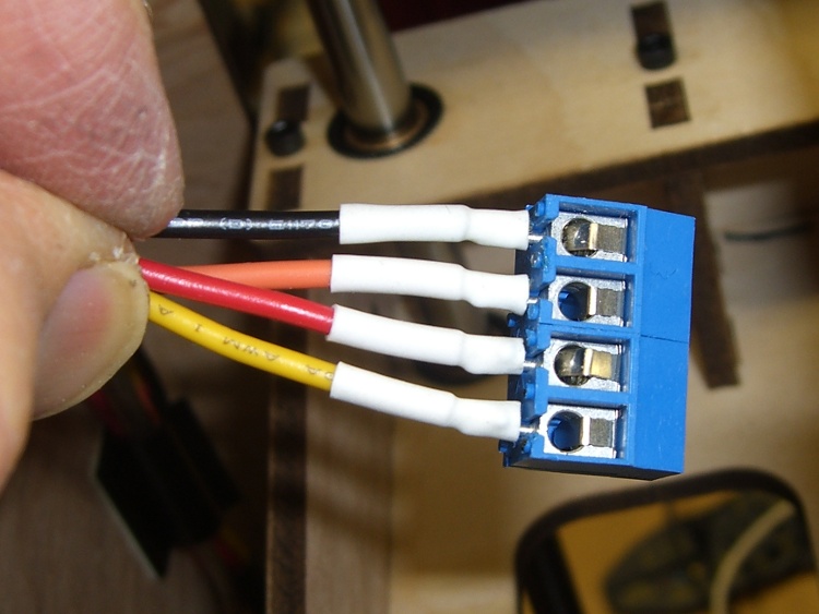
The first step is to route the 4-pin ATX power connector (which popped off the big connector block plugged into the Motherboard) out the left-rear hole in the acrylic floor under the XY stage. I don’t have a mating connector, so I conjured up something from the same square pins as I used in the Extruder power supply modification and some wire harvested from a dead ATX supply. The black heatshrink tubing holds the four wires and their pins in the proper configuration. Obviously, you want matching colored wires, because the “connector” isn’t polarized!
On the other end, a four-pin screw terminal block provides a convenient way to attach a variety of gadgetry. At last count, it serves the exhaust fan, +5 V dummy load, LED platform light, and a cooling fan. More details on those later…
Terminal Block
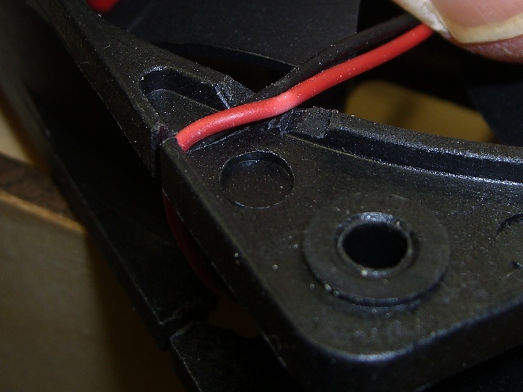
The fan frame required a small gouge to route the wire inward through the vent hole in the side of the TOM case:
Fan frame modification
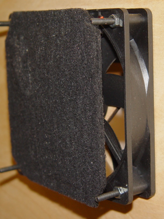
Four nuts secure the fan to the frame. Fortunately, the fan’s motor housing sits on the exhaust end, so the filter material rests against the hub support and spider. Here’s what the whole arrangement looks like, with the filters pried away from the fan.
Fan and filter mounting
A trip to the local Big Box home warehouse produced a $10 20×25-inch activated charcoal air filter intended for a whole-house air conditioner. I now have a large plastic grid, a sheet of open-cell foam air filter, plus a generous supply of charcoal filter material. I cut a 4-3/4-inch strip from one side, chopped it into 4-3/4-inch squares (that’s 120 mm everywhere else in the world), trimmed off the corners, tucked two layers behind the TOM filter holder frame, and added four more nuts-and-washers.
The spare filter material goes in a sealed plastic bag, because activated carbon has a limited lifetime when exposed to free air. That’s what it does for a living: adsorb smelly molecules from passing air!
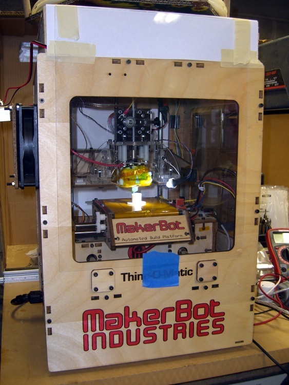
The final step is to close off all the TOM’s openings, thus restricting air flow through the case. This has the happy side effect of warming the build area and reducing drafts, both quite important in a wintery 50-ish °F basement. Taking pictures of clear acrylic sheet is essentially impossible, but you can see the front piece there and the paper seals around the filament spool there. I make no apology for the masking tape; after everything’s working, I’ll formalize the arrangements.
Incidentally, don’t get too secure with the front window, because the ABP pokes through the opening to disgorge finished parts. In fact, the front of the ABP whacks the window when the nozzle reaches the back of the ABP, so you don’t want a mechanical latch holding the window closed.
I’m thinking a magnetic latch is in order.
There’s enough leakage around the windows to keep the fan happy, although it sucks the last one closed. Those four square cable holes in the acrylic sheet between the upper and lower chambers provide the only air channels, so the exhaust fan probably doesn’t compete with the ATX supply’s cooling fan.
While the filter doesn’t kill off all the stink, the TOM is a much better companion now…
The inside of a Thing-O-Matic gets pretty dark, particularly with the Lazy Susan spool parked on top, so I added a spot light to the Z stage.
The alternative seems to be LED strip lighting all over the inside, but my Parts Heap doesn’t have any of those yet and it did have a 10 mm white LED. The thing runs at 100 mA, so a 15 Ω 1/2 W resistor (to a +5V tap), a few snippets of heat-shrink tubing, and a blob of hot-melt glue did the trick.
Some sculpture armature wire that’s been kicking around for years holds the LED (wrap it around, add hot-melt glue) and doesn’t mind the occasional bump. I crimped the wire in a solderless connector and grabbed it in one of the Extruder Frame screws. It’s allegedly fatigue-proof, but it looks a lot like aluminum.
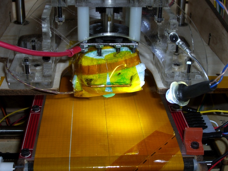
A bit more detail, with a Kapton-and-graph-paper belt (about which, more later) on the ABP:
The laser-cut plywood clamps holding the timing belts to the drive ribs slant diagonally across the rib + belt and secure one edge of the belt.
Belt clamp before modification
While this certainly works, it offended my sensibilities and is probably why the instructions call for that low-profile bolt.
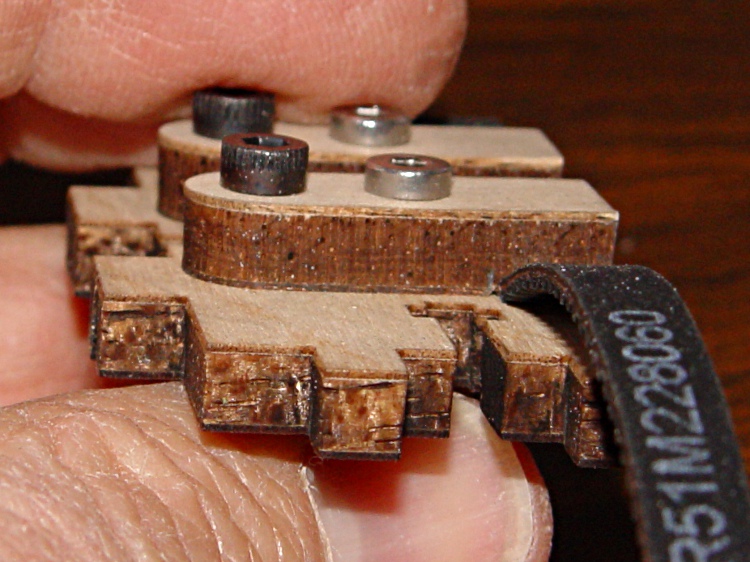
Introducing the belt clamp to Mr Disk Sander provided just enough relief to clear the belt’s backing, while not making for a sloppy fit. In round numbers, if you barely trim off the plywood veneer it’ll be about right. Use an ordinary file if one of Mr Sander’s relatives doesn’t live in your shop.
Modified belt clamp
And then it works just like it should. If you were even fussier, you might chamfer the outer edges to allow the belt to lie flatter against the rib, but that’s in the nature of fine tuning. At least on my Thing-O-Matic, there’s plenty of air between a standard bolt head and the adjoining carrier rod.
Modified belt clamp in place
This is obviously not something you should dismantle your Thing-O-Matic for, but if you’re in the delightful position of facing that mountain of parts, this is perfect timing.