Ed Nisley's Blog: Shop notes, electronics, firmware, machinery, 3D printing, laser cuttery, and curiosities. Contents: 100% human thinking, 0% AI slop.
Both of those “projects”, which may be too grand a term, went from “I need a thing” to having one in hand over the course of a few minutes yesterday. Neither required a great deal of thought, having previously worked out the proper speed / power settings to cut 3 mm MDF and 1 mm cork.
Other folks may lead you to believe lasers are all about fancy artwork and elaborate finished products. Being the type of guy who mostly fixes things, I’d say lasers are all about making small and generally simple parts, when and where they’re needed, to solve a problem nobody else has.
Perhaps I should devote more attention to using fancy wood with a hand-rubbed wax finish, but MDF fills my simple needs.
With a laser and a 3D printer, shop tools have definitely improved since the Bad Old Days!
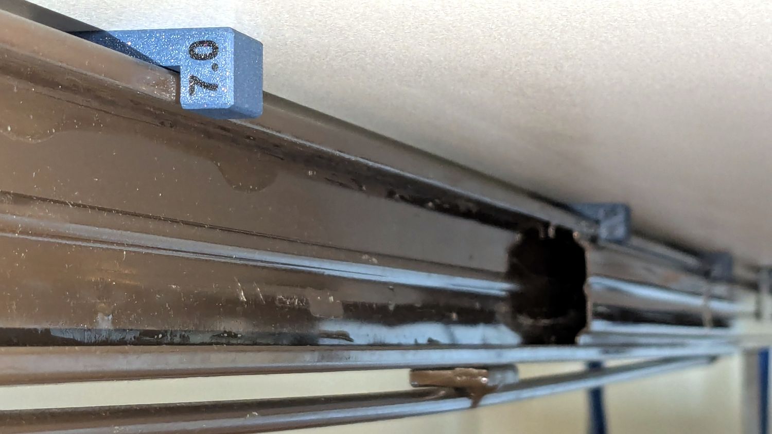
The Handi-Quilter HQ Sixteen rides on two tracks along the 11 foot length of the table, with an unsupported 8 foot span between the legs on each end:
HQ Sixteen – remounted handlebars in use
Contemporary versions of the table have support struts in the middle that our OG version lacks and, as a result, our table had a distinct sag in the middle. During the course of aligning the table top into a plane surface with tapered wood shims, I discovered the floor was half an inch out of level between the table legs.
Now that the whole thing has settled into place, I measured the shim thicknesses and made tidy blocks to replace them:
HQ Sixteen – table shims – finished
The OpenSCAD code has an array with the thickness and the number of blocks:
Yes, I call them “blocks” here and wrote “shims” in the code. A foolish consistency, etc.
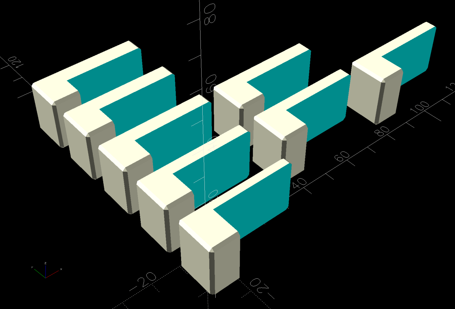
The model is a chamfered block with a chunk removed to leave a tongue of the appropriate thickness:
HQ Sixteen – table shims – solid model
Building them with the label against the platform produces a nice nubbly surface:
HQ Sixteen – table shims – PrusaSlicer – bottom
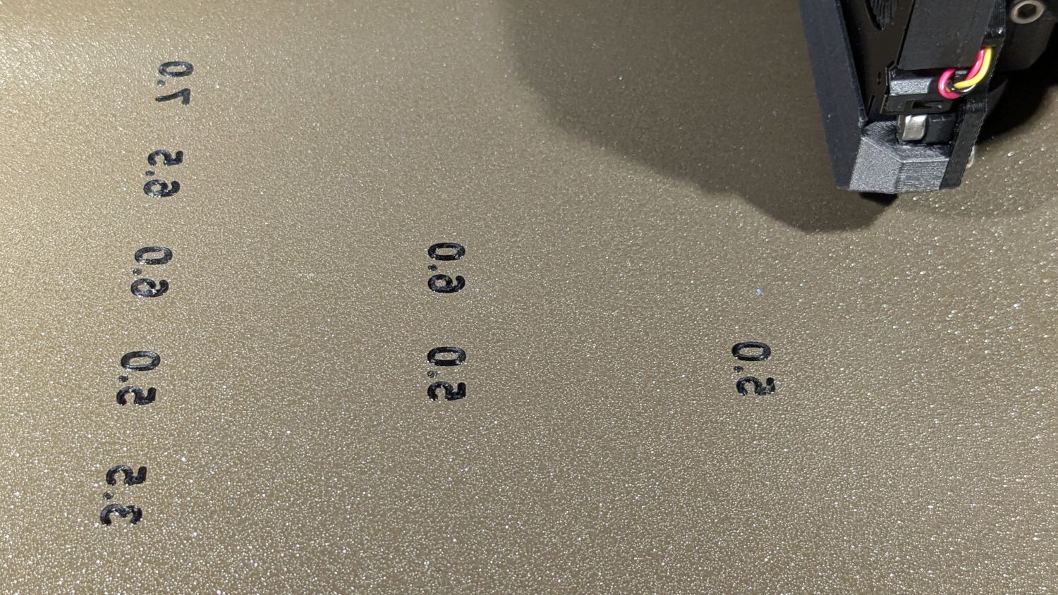
The labels print first and look lonely out there by themselves:
HQ Sixteen – table shims – legends
The rest of the first layer fills in around the labels:
HQ Sixteen – table shims – first layer
Putting the labels on the bottom makes the wipe tower only two layers tall and eliminates filament changes above those layers. Those eight blocks still took a little over three hours, because there’s a lot of perimeter wrapped around not much interior.
Having had the foresight to draw a sketch showing where each block would go, I slid one next to its wood shim, yanked the shim out, and declared victory:
HQ Sixteen – table shims – installed
The tension rod welded under the table rail prevents even more sag, but the struts under the new version of the table show other folks were unhappy with the sag of this one. Another leg or two seems appropriate.
With the table leveled and the surface aligned, the HQ Sixteen glides easily in all directions. The result isn’t perfect and Mary keeps the anchor block at hand, but the machine now displays much less enthusiasm for rolling toward the middle of the table.
The OpenSCAD source code as a GitHub Gist:
This file contains hidden or bidirectional Unicode text that may be interpreted or compiled differently than what appears below. To review, open the file in an editor that reveals hidden Unicode characters.
Learn more about bidirectional Unicode characters
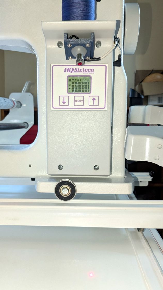
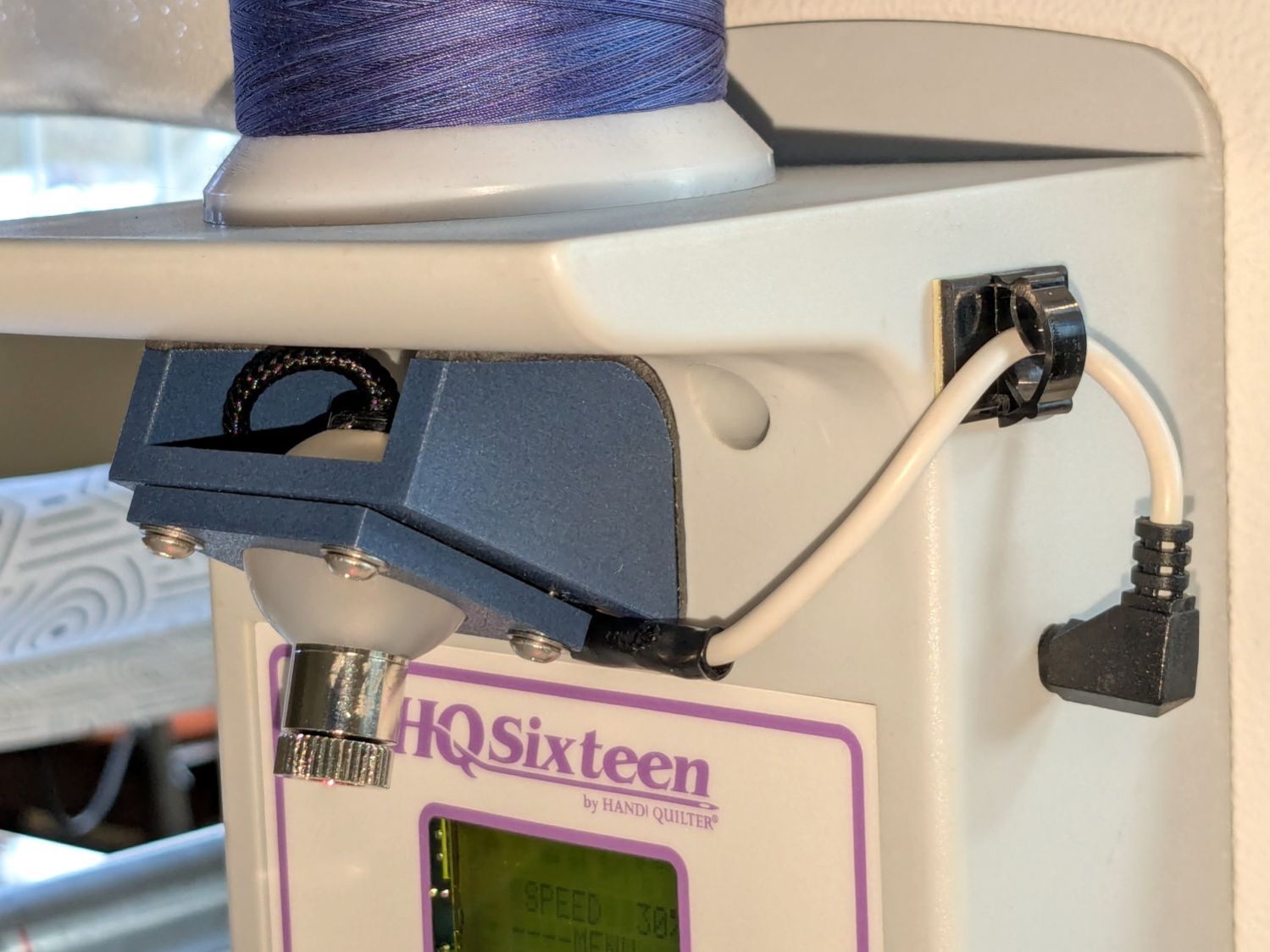
Installing the new ball-mount laser stylus on the HQ Sixteen’s electronics pod required nothing more than two strips of good foam tape:
HQ Sixteen – Stylus Laser – installed – overview
In actual use, you would:
Lay down a “pantograph” pattern on a paper strip along the rear track under the machine’s carriage
Position the needle at the appropriate spot on the quilt
Aim the laser at the corresponding point on the pattern
Start the machine!
Move the laser spot along the pattern while the machine stitches that pattern in the quilt
Mary thinks free-motion quilting is easier and I’m not in a position to argue the point.
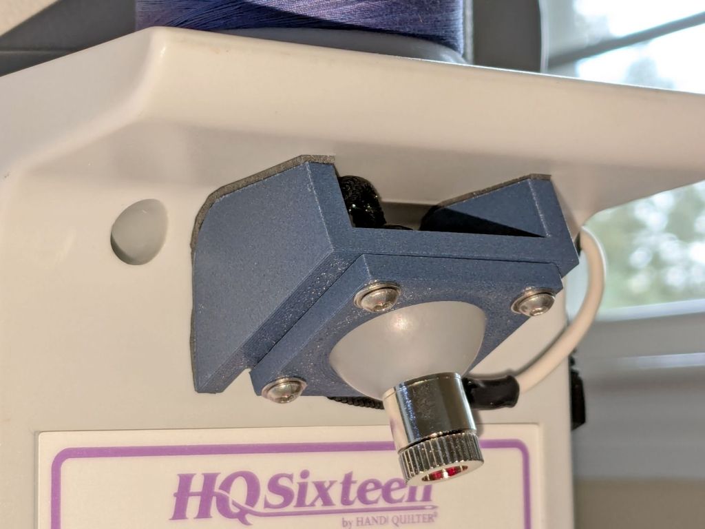
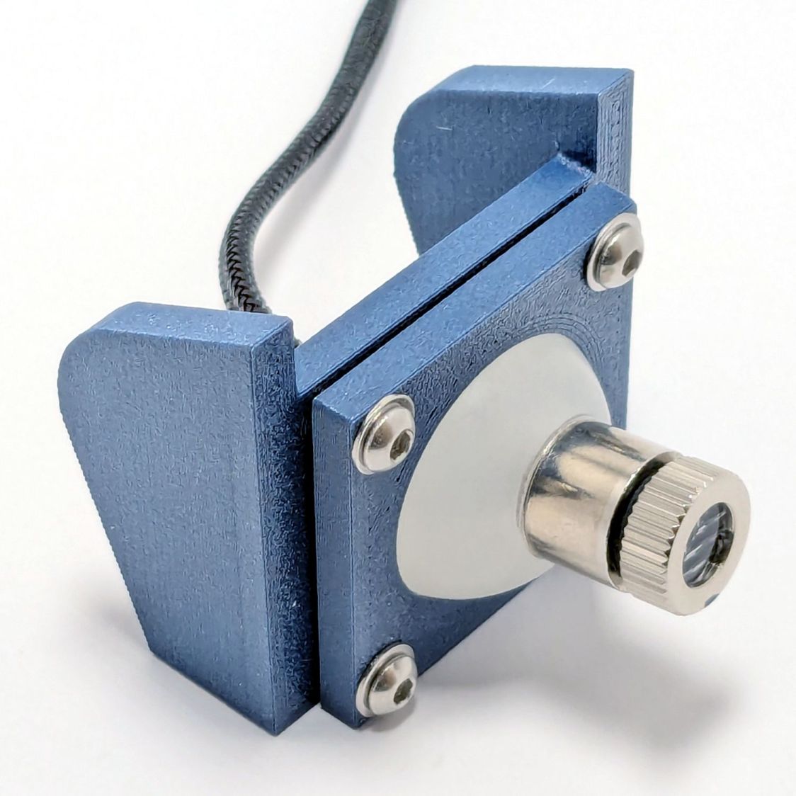
Anyhow, the key feature of my ball mount is that it’s completely out of the way:
HQ Sixteen – Stylus Laser – installed – front
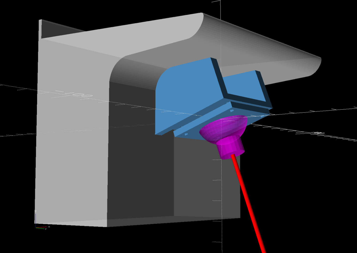
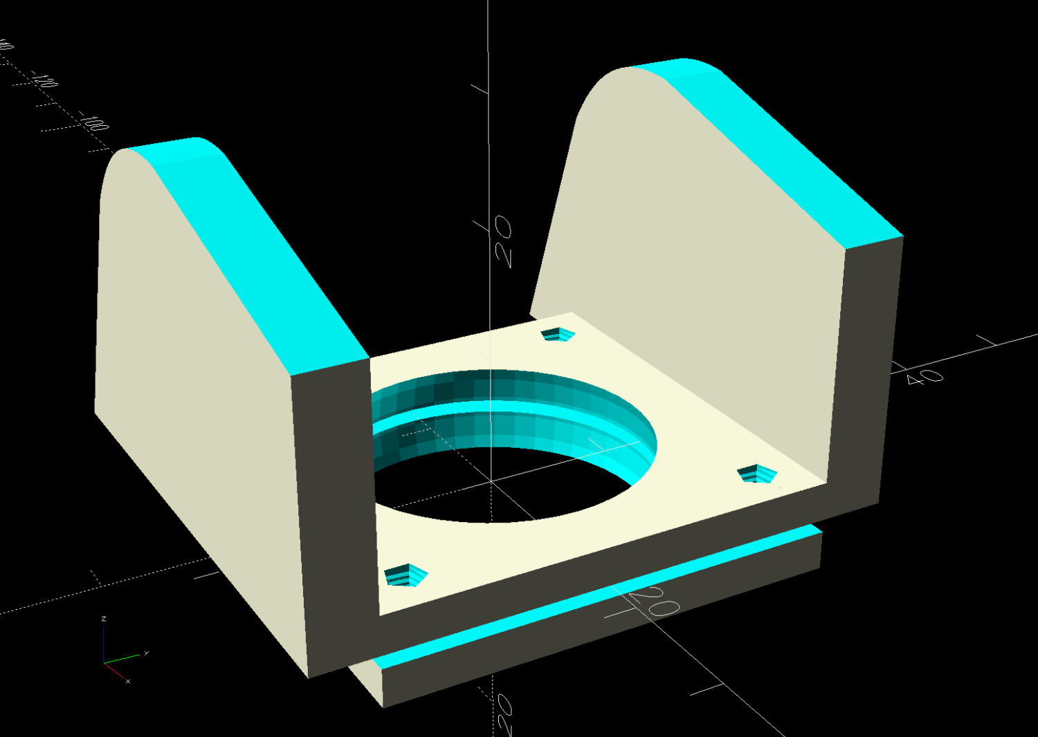
Which looks comfortingly like the original solid model:
HQ Sixteen – Stylus Laser Mount – solid model – show
Minus the vivid red death ray and pew! pew! pew!
Power comes from a barrel jack in the back intended for the original stylus laser; all small lasers, unless otherwise noted, run from 5 VDC. The jack is 3.5×1.3 mm, but the Drawer o’ Weird Barrel Plugs disgorged a matching right-angle plug. Unsurprisingly, such things are readily available these days.
Splice the laser leads to the plug and cover the evidence with a braided loom + heatshrink tubing:
HQ Sixteen – Stylus Laser – installed – rear
I considered a switch, but the anticipated low duty cycle suggested just unplugging it, so that’s that.
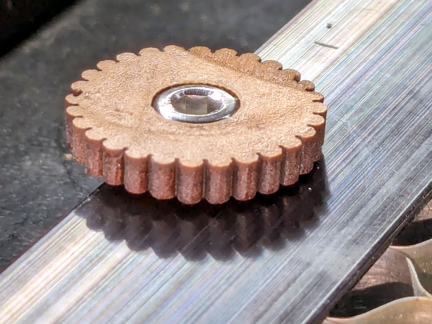
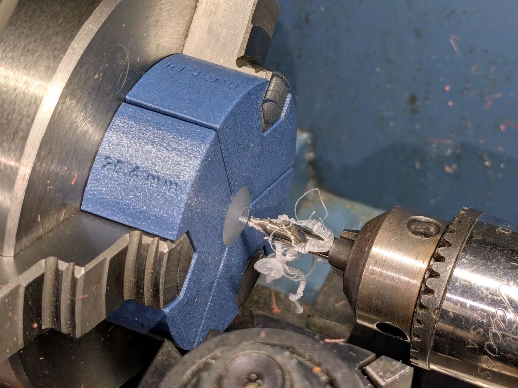
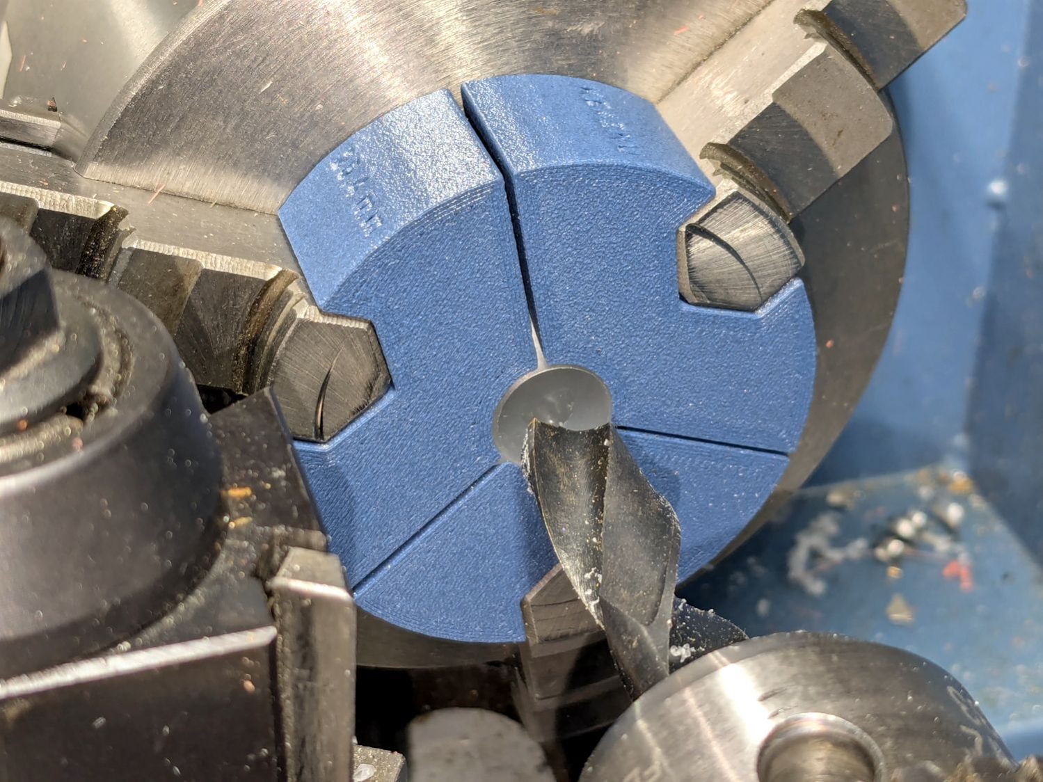
Start by conjuring a lathe chuck fixture for a 1 inch ball from my OpenSCAD model and printing it in PETG-CF:
HQ Sixteen – Stylus Laser – center drilling
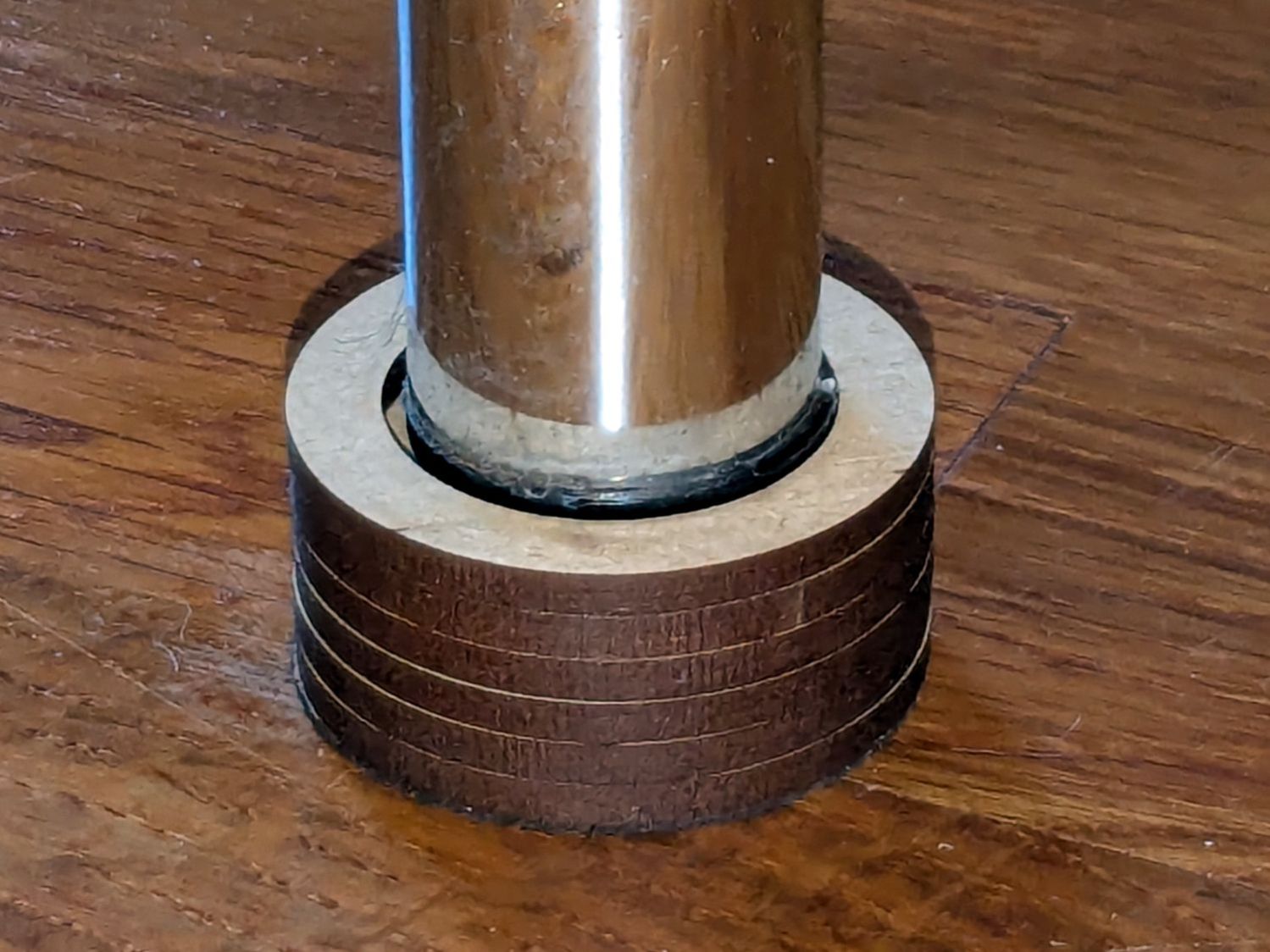
Run a few drills through the ball up to 15/32 inch = 0.469 inch = 11.9 mm:
HQ Sixteen – Stylus Laser – final drilling
Which looks terrifying and was no big deal.
The laser module didn’t quite fit until I peeled off the label, as setting up a boring bar seemed like too much hassle for too little gain. The ball is slick polypropylene and the laser module is chromed plastic, which means there’s not much friction involved and a stiff fit is a Good Thing™.
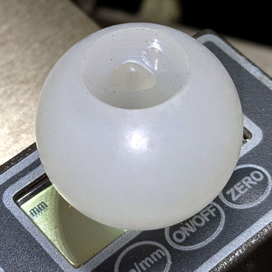
I did not realize the hazy white patches barely visible inside the ball were voids / bubbles:
HQ Sixteen – Stylus Laser – drilled ball
Next time I’ll (try to) orient the patches toward the tailstock in hopes of simply drilling through them to leave solid plastic around the rim.
Ramming the laser in place makes it look like it grew there;
HQ Sixteen – Stylus Laser – laser test fit
The alert reader will note the lens projects a line, due to my not ordering any dot modules back when I got a bunch of these things. After all, who wants a plain dot when you can light up a line or even a crosshair?
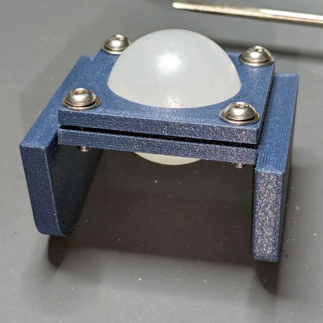
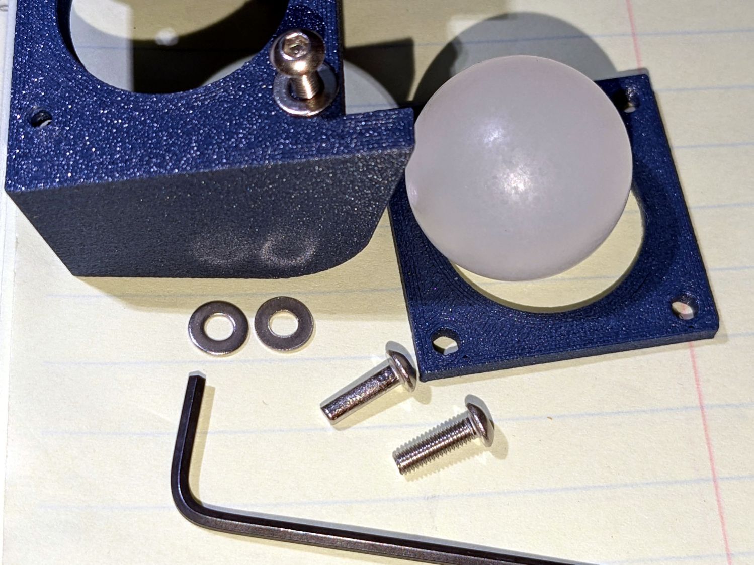
The plates have a sphere subtracted from them and a kerf sliced across the sphere’s equator for clamping room:
HQ Sixteen – Stylus Laser Mount – solid model
Given that this is a relatively low-stress situation, I embedded BOSL2 nuts to produce threads in the plate rather than use brass inserts.
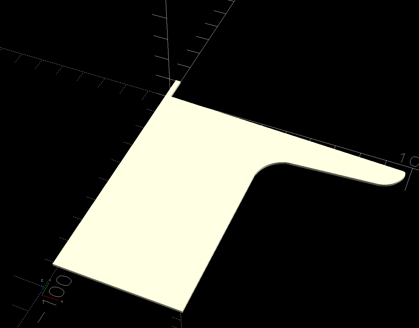
The side plates start as simple rectangles:
HQ Sixteen – Stylus Laser Mount – solid model – mount sides
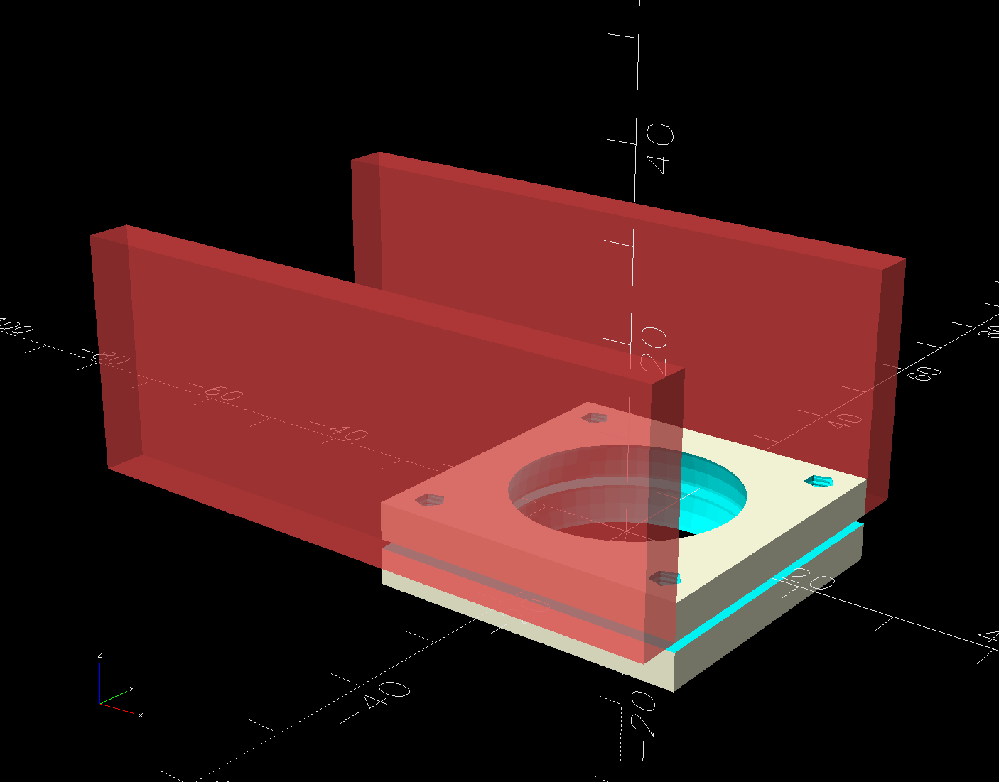
Subtracting the electronics pod shape from those slabs matches them exactly to the curvalicious corner:
HQ Sixteen – Stylus Laser Mount – solid model – mount shaping
The weird angle comes from tilting the mount to aim the laser in roughly the right direction when perpendicular to the plates:
HQ Sixteen – Stylus Laser Mount – solid model – show
That angle can be 0° to 30°, although 25° seems about right. The slab sides neither stick out the top nor leave gaps in the corner over that range, after some cut-and-try tinkering sizing.
One of the M3 screws just did not want to go into its hole:
This file contains hidden or bidirectional Unicode text that may be interpreted or compiled differently than what appears below. To review, open the file in an editor that reveals hidden Unicode characters.
Learn more about bidirectional Unicode characters
The pin can go into either of a pair of threaded holes in the machine castings or the laser + clamp can, as in the picture, attach to a spool pin.
With a “pantograph” pattern laid along the rear of the table, you can stitch that design (at full size, hence “pantograph” seems aspirational) by guiding the red dot along the lines. The laser’s flimsy clamp mount seems prone to move at the worst possible moment, so neither of us liked the idea.
Mary is good at free-motion quilting and says she’s unlikely to use the laser, but I figured staying slightly ahead of the curve would be a Good Idea. Bonus: 3D printing.
The general idea is to tuck a (similar) red-dot laser module under the overhang of the electronics pod, with a ball mount for easy aiming and stable setting, something like this:
HQ Sixteen – Stylus Laser Mount – solid model – show
Fitting the mount into that curved corner requires a model of the electronics pod, so I held a pad of paper against the pod and traced the outline:
HQ Sixteen – pod profile trace
Scan it, import the image into Inkscape, fit lines and curves around the shape:
HQ Sixteen – pod outline – Inkscape
I only needed the top of the pod, so the bottom is truncated from the actual 250 mm height.
Save the SVG, import into OpenSCAD, extrude to match the pod’s 110 mm width:
The model origin is where the upper lip meets the slightly sloped top surface in the middle of the extrusion, because that’s the only easy-to-locate feature:
HQ Sixteen – Stylus Laser Mount – electronics pod – solid model
Something Has Changed in the Inkscape SVG → OpenSCAD model chain, because the parts of an Inkscape drawing lying outside the page boundary are no longer cropped from the OpenSCAD model. Now, simply putting a feature at the Inkscape origin at the lower-left corner of the document’s Page produces a complete OpenSCAD 2D shape with that feature at the 3D coordinate origin.
The Inkscape layout with the entire shape off the page:
HQ Sixteeen – pod profile – Inkscape origin
The 2D imported shape in OpenSCAD with a matching origin:
HQ Sixteeen – pod profile – Inkscape origin
I do not know what changed or if, in fact, my misunderstanding of how things worked required the previous workaround, but this is much better. The OpenSCAD code includes a [0,0] offset value, should you need it.
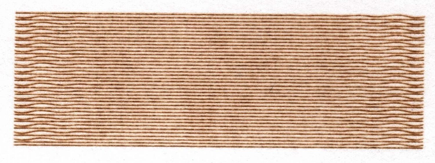
The rectangle is 30×10 mm, with lines spaced 0.25 mm apart to simplify estimating distances (although I also have a measuring magnifier) and run at 100 mm/s to simplify converting distance to time. The lines alternate in direction, beginning with a left-to-right line at the bottom (which is bar-straight from the initial positioning move). The wobbles occur at the start of each line.
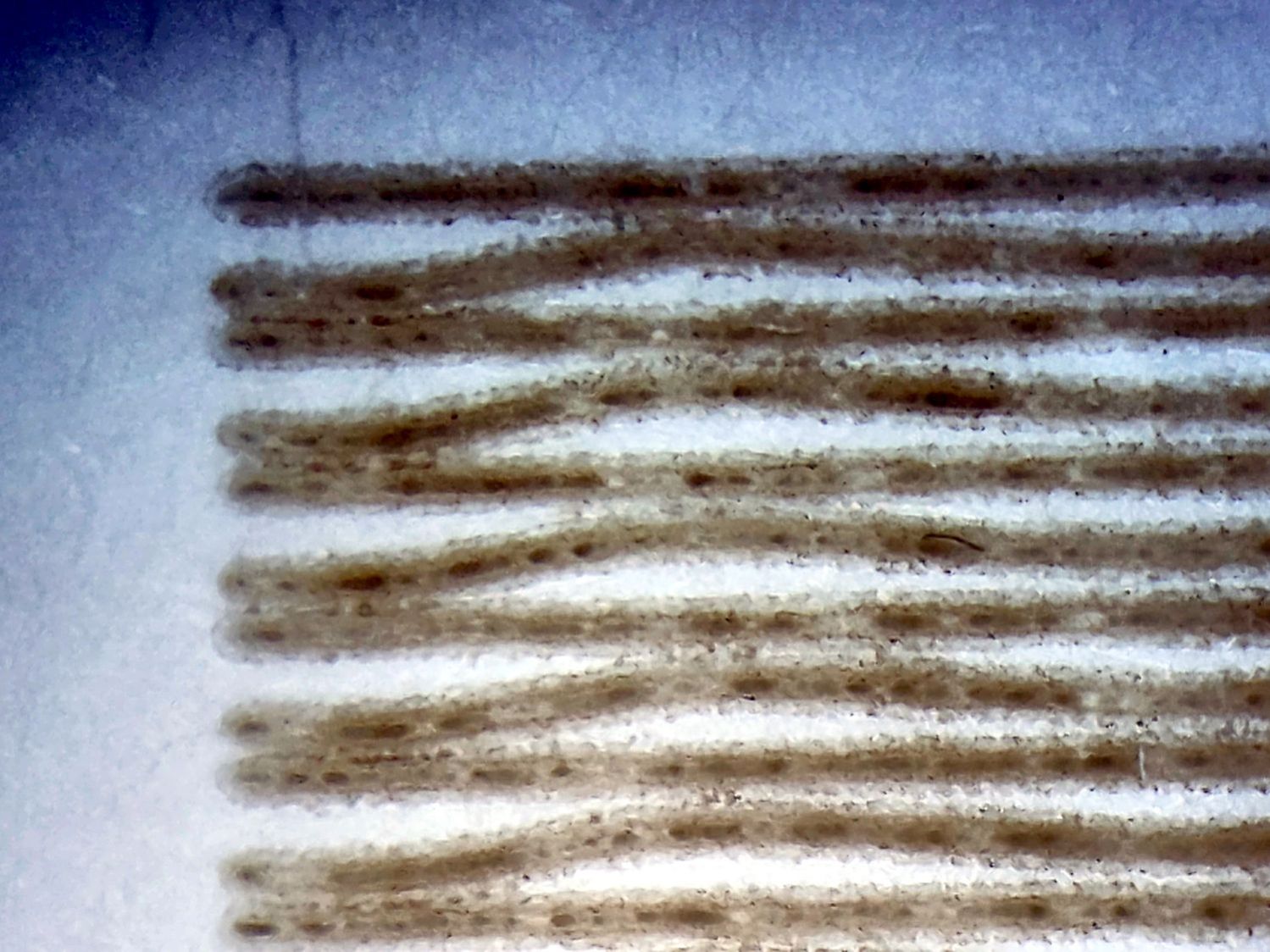
A closer look with blown contrast:
Engraving – 100mm-s 0.25mm interval 9pct – detail
The maximum error in the Y axis direction looks like 0.12 mm and damps out after 3 cycles. Each cycle covers 2.8 mm = 28 ms = 35 Hz.
The LightBurn Preview shows a 1.5 mm overscan distance and extrapolating the wobbulations leftward suggests the gantry starts the scan line with an overshoot due to the Y axis motion. The cycle-to-cycle damping is about 50%, so the initial overshoot (invisible in the overscan region) might be 0.25 mm, agreeing reasonably well with the 0.2 mm seen while cutting small squares.
The results above come from these settings:
Layer speed: 100 mm/s
Line interval: 0.25 mm
Y acceleration: 2000 mm/s²
Y start speed: 20 mm/s
I then made single-variable changes to the Engraving Parameters settings:
Line shift speed
500 mm/s
10 mm/s
Y Acceleration
200 mm/s²
Y start speed
30 mm/s
Today I Learned: The Y Start Speed (in mm/s) for engraving is capped by the Y Axis Jumpoff Speed (in mm/s², so perhaps the maximum change in speed), which is, in turn, capped at 80 mm/s.
Each of the variations produced a result visually indistinguishable from the image you see above: the error magnitude and oscillation frequency were identical.
One possible reason: None of those settings have any effect, because LightBurn doesn’t do whatever the Ruida controller defines as Engraving. However, changing both the Y start speed and the Jumpoff speedshould have made at least a little change to the results and did not.
Another possible reason: Each 0.25 mm Y axis change requires 20.8 motor steps (either 20 or 21 at 12 µm/step), so the fancy tweaks lack space to take effect, the motor thumps 20-ish steps, and the gantry shakes the same way every time.