This definitely isn’t ready for prime time, but it’s already much better than the manual process and a few notes are in order.
The general idea is to have a Python program generate a set of SVG images, each one describing a single layer of paper in the stack:

As expected, there’s a Python SVG library handling the details of creating SVG images.
Define a bunch of “constants” with all the physical measurements and suchlike:
PageSize = (round(8.5*INCH,3), round(11.0*INCH,3))

SheetCenter = (PageSize[X]/2,PageSize[X]/2)     # symmetric on Y!

SheetSize = (200,200)           # overall sheet

AlignOC = (180,180)             # alignment pins in corners
AlignOD = 5.0                    #  … pin diameter

MatrixOA = (170,170)            # outer limit of cell matrix

CellCut = "black"               # C00 Black
SheetCut = "red"                # C02 Red
HeavyCut = "rgb(255,128,0)"     # C05 Orange        black mask paper is harder
HeavyCellCut = "rgb(0,0,160)"   # C09 Dark Blue     ditto
Tooling = "rgb(12,150,217)"     # T2  Tool

DefStroke = "0.2mm"
DefFill = "none"
Then marking the middle of the layout with that little circle looks like this:
ToolEls = []                    # accumulates tooling layout
# mark center of sheet for drag-n-drop location
ToolEls.append(
    svg.Circle(
        cx=SheetCenter[X],
        cy=SheetCenter[Y],
        r="2mm",
        stroke=Tooling,
        stroke_width=DefStroke,
        fill="none",
    )
)
Cutting the perimeter and four alignment holes:
SheetEls = []                   # accumulates sheet cuts
# cut perimeter
SheetEls.append(
    svg.Rect(
        x=as_mm(SheetCenter[X] - SheetSize[X]/2),
        y=as_mm(SheetCenter[Y] - SheetSize[Y]/2),
        width=as_mm(SheetSize[X]),
        height=as_mm(SheetSize[Y]),
        stroke=SheetCut if ThisLayer > 0 else HeavyCut,
        stroke_width=DefStroke,
        fill="none",
    ),
)
# cut alignment pin holes except on mask layer
if ThisLayer > 0:
    for c in ((1,1),(-1,1),(-1,-1),(1,-1)):
        SheetEls.append(
            svg.Circle(
                cx=as_mm(SheetCenter[X] + c[X]*AlignOC[X]/2),
                cy=as_mm(SheetCenter[Y] + c[Y]*AlignOC[Y]/2),
                r=as_mm(AlignOD/2),
                stroke=SheetCut,
                stroke_width=DefStroke,
                fill="none",
            )
        )
Burning the layer ID in binary:
# cut layer ID holes except on mask layer
if ThisLayer > 0:
    c = ((1,1))
    h = f'{ThisLayer:0{Layers.bit_length()}b}'
    for i in range(Layers.bit_length()):
        SheetEls.append(
            svg.Circle(
                cx=as_mm(SheetCenter[X] + c[X]*AlignOC[X]/2 - (i + 2)*AlignOD),
                cy=as_mm(SheetCenter[Y] + c[Y]*AlignOC[Y]/2),
                r=AlignOD/4 if h[-(i + 1)] == '1' else AlignOD/8,
                stroke=SheetCut,
                stroke_width=DefStroke,
                fill="none",
             )
        )
Filling the matrix of blocks with random numbers turned out to be a one-liner:
CellMatrix = [[randint(1,args.colors) for _ in range(args.height)] for _ in range(args.width)]
That matrix is a constant for all the layers, which is why you must feed the program the same random number seed to generate the layers.
Given the layer number and that matrix, deciding what to do for each hole is a walk through the cells:
MatrixEls = []                  # accumulates matrix cuts
for i in range(args.width):
    x =i*CellOC[X]
    for j in range(args.height):
        y = j*CellOC[Y]

        if ThisLayer == 0:                          # black mask
            s = HeavyCellCut
        elif ThisLayer < CellMatrix[i][j]:          # rest of sheets above color layer
            s = CellCut
        else:
            s = Tooling                             # at or below color layer

        MatrixEls.append(
            svg.Rect(
                x=as_mm(SheetCenter[X] - MatrixOA[X]/2 + x),
                y=as_mm(SheetCenter[Y] - MatrixOA[Y]/2 + y),
                width=as_mm(CellSize[X]),
                height=as_mm(CellSize[Y]),
                stroke=s,
                stroke_width=DefStroke,
                fill="none",
            )
        )
After accumulating all the other elements in similar lists, this creates and emits the entire SVG file to stdout:
canvas = svg.SVG(
    width=as_mm(PageSize[X]),
    height=as_mm(PageSize[Y]),
    elements=[
        ToolEls,
        SheetEls,
        MatrixEls
    ],
)

print(canvas)
The whole program has a bit more going on, but those are the high points.
Invoke the program with a Bash one-liner:
for i in {00..08} ; do python Layers.py --layernum=$i > Test_$i.svg ; done
That produces nine SVG image files that you import into LightBurn and arrange in a tidy array:

I discovered that holding down the Shift key while importing the SVG files stacks them at the workspace origin (the upper-right corner for my machine) in the order of the file names, so clicking on the stack selects successive layers in the right order; just drop each one wherever you need it, then tidy the lineup.
The Python program sets the vector stroke colors using LightBurn palette values, so that LightBurn automagically assigns them to the appropriate layers. It turns out the black paper I used for the mask requires different speed / power values than the other colored paper.
I put the alignment features on a different layer than the matrix holes to make them more visible, even though they have the same speed / power values.
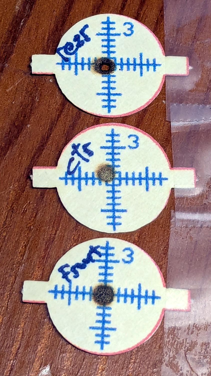
Align the template so the middle of the layer pattern is in the middle of the grid, then use LightBurn’s Print and Cut to align the template with the fixture on the laser platform:

Then the process requires just a few clicks per layer:
- Drop a sheet of paper into the fixture
- Click to select a layer layout
Ctrl-Dto duplicate itPto snap it to the middle of the gridAlt-Sto Fire The LaserDelto delete that layer (which is why it’s a duplicate!)- Iterate until done!
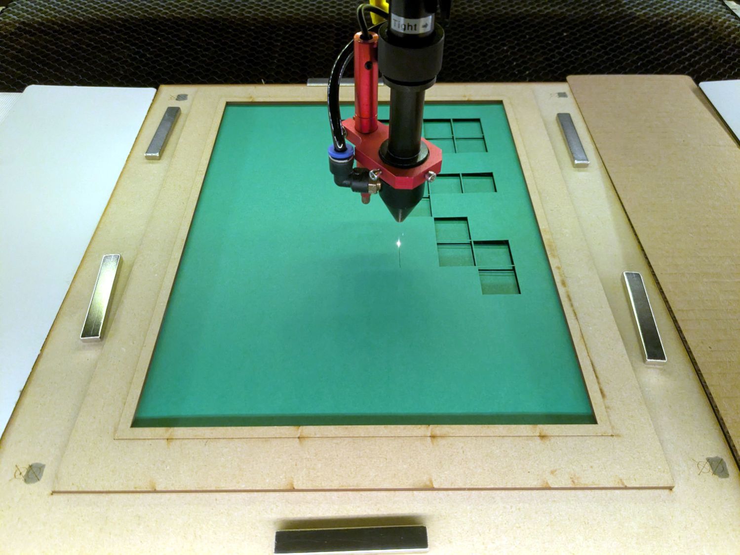
Which looks pretty much like you’d expect:
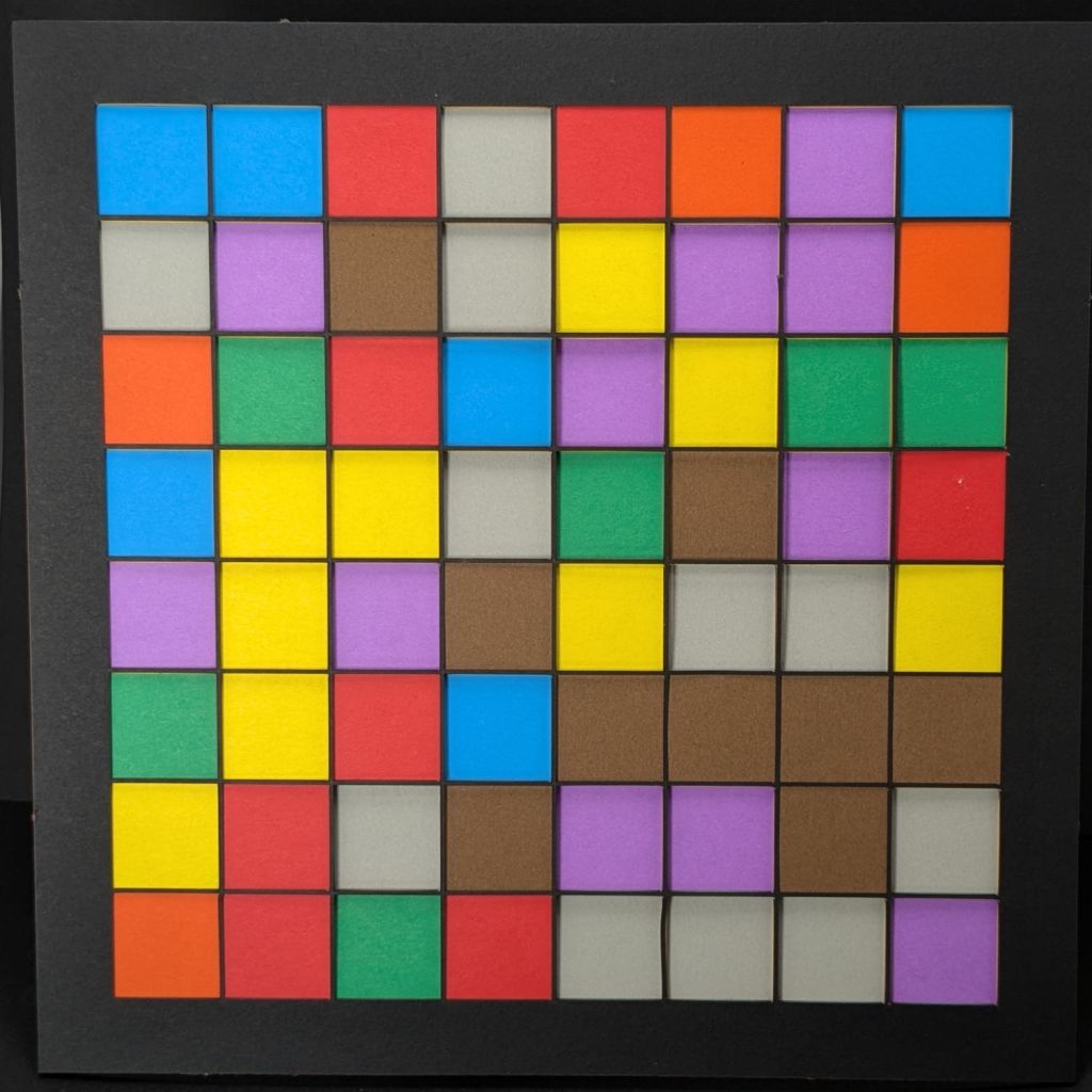
Take the stack of paper to the workbench, use an Xacto knife to cut the tabs holding the square into the Letter page, apply glue stick, stack in the fixture, and iterate to create a solid sheet with lots of holes:
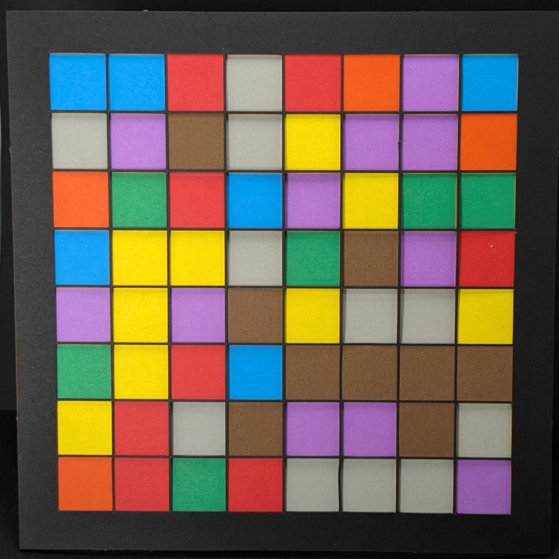
More refinement is in order, but that’s the overview …


