Being the type of guy who uses metal bits & pieces, I thought this might be a useful aluminum rod:
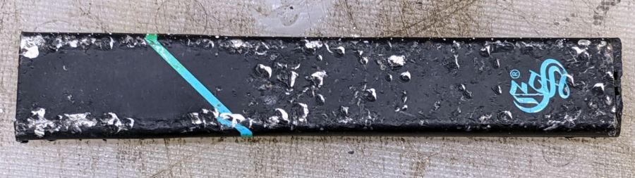
It turns out to be an aluminum tube holding a lithium cell and a reservoir of oily brown juice:
The black plastic cap read “EonSmoke”, which led to a defunct website at the obvious URL. Apparently, EonSmoke went toes-up earlier this year after ten years of poisoning their customers, most likely due to “competitor litigation”.
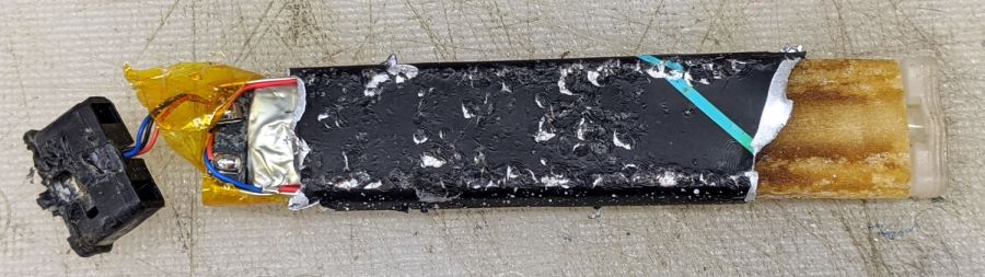
The black cap held what looks like a pressure switch:

Suck on the icky end of the tube to activate the switch, pull air past the battery (?), pick up some toxic vapor around the heater, and carry it into your lungs:

Maybe there’s a missing mouthpiece letting you suck on the icky end, activate the switch, pull vapor through the heater, and plate your lungs with toxic compounds. I admit certain aspects of my education have been sadly neglected.
The lithium cell was down to 1.0 V, with no overdischarge protection and no provision for charging, so it’s a single-use item. I’m sure the instructions tell you to recycle the lithium cell according to local and state regulations, not toss it out the window of your car.
I had to wash my hands so hard …