Ed Nisley's Blog: Shop notes, electronics, firmware, machinery, 3D printing, laser cuttery, and curiosities. Contents: 100% human thinking, 0% AI slop.
Maybe it’s just me, but all of the laser pointers I’ve bought, even the relatively spendy ones, have crappy switches and unstable battery contacts.
For example, this is the business end of a $12 (!) pen-style pointer. The battery contact was off-center and poorly secured; I pried the white plastic retainer out, bashed the spring into submission, and replaced the retainer with a length of heat-shrink tubing. It wasn’t pretty.
This pointer has an actual mechanical switch module inside, with a clicky mechanism actuated by the external button. Cheaper pointers seem to rely on bare PCB contacts bridged by the button’s base. Ugh.
Laser pointer battery orientation: positive DOWN
Memo to Self: The AAA cells fit into the housing with the positive terminal away from the laser head. The white plastic plug has a molded cross that could be mistaken for a + symbol, but it’s not.
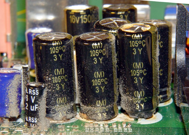
A friend dropped off a dead eMachines Celeron for my next recycling trip. Peering inside, what do my wondering eyes behold but a nasty case of Capacitor Plague!
Herewith, some pix of the victims within the box. Note the bulging tops ready to blow along the pressure-relief grooves, the distinct tilt caused by the bulging bottom plug, and the right-hand cap near the power supply on countdown for launch!
When you don’t need high optical quality for an IR filter, you can superimpose red and blue stage-lighting filters: pure black to the eye, transparent to IR.
You know they’re IR-transparent because they’re generally snuggled right up against huge incandescent bulbs: if the filter material absorbed any IR, it’d burn right up.
I’ve used Lee Filters Congo Blue (181) and Primary Red (106) to good effect. They may be available from a stagecraft outlet near you, but around here that stuff is a mailorder deal. You’ll get a lifetime supply, so maybe you can pass some out to your cronies; techies always enjoy odd presents like that.
A more optically flat (and durable and expensive) option would be a photographic-image-quality glass IR filter suitable for camera mounting. I got one after I dropped a homebrew plastic filter down a sewer grate.
For examples, go to Adorama, click on Filters in the left column, then select Infra-Red Filters, then maybe refine the search to the cheaper Hoya brand before your budget runs away in fear.
Gel filters – IR view with visible light
Make sure your camera doesn’t have an IR blocking filter behind the lens. I think most consumer-grade digital cameras do have an IR-blocking filter and most video cameras don’t, but I’m sure those general rules don’t hold in all cases. Indeed, I bought a Sony DSC-F717 specifically for its IR mode; fortunately, the CCD sensor failed shortly before the factory recall ended.
The pictures show the same scene under normal lighting, with the camera set to its IR mode, and IR mode with an IR filter in front of the lens.
The gel filters appear dark-gray in the middle image because the camera sets the exposure (1/60 f2.4 ISO100) based on the visible light entering the lens. They’re transparent in the bottom image because the exposure (1/30 f2.4 ISO1000) is based on only the IR illumination, which is pretty dim. The gratuitous greenish cast is how Sony reminds you that the image was in IR mode
Back in 2000, I replaced the ballast in our bathroom light; the old one failed after a mere 45 years. The casing didn’t sport any PCB-free labels (no surprise there), so I disposed of the carcass at a town hazmat day.
Under normal circumstances you’d replace the whole fixture, but this is a slender 4-foot chromed steel base with a matching chromed shield over a 4-foot fluorescent tube: charming, in a retro-mid-50s sort of way. We couldn’t find anything suitable at the local big-box home supply stores, so I just cleaned it up and stuck a new ballast inside.
I indulged in the luxury of a warm-white tube so I didn’t look quite so dead in the morning.
That ballast just failed, after a mere 9 years, which I confirmed by swapping in a new tube. It seems nothing lasts any more.
We went through the same “should we get a new fixture?” exercise and, unwilling to drop more than $150 on a really cheesy two-tube fixture that would be way too bright, I bought Yet Another Ballast from, oddly enough, the same manufacturer and possibly even the same Mexican town.
This time I got an electronic ballast, with an A sound rating which comes mostly for free without that big magnetostrictive iron core. Costs twice what the magnetic ballast does, but I figure you only go around once, right?
It comes with a scary label telling you to insulate the unused lead (it can drive two tubes) “for 600 V”. That turns out to be the standard wire-nut rating, so I clipped off the exposed copper end and screwed the nut in place over the insulation. Wired the leads up per the diagram and that’s the end of that story.
Now, I’m here to tell you that going from a nearly dead magnetic ballast to a shiny new electronic ballast is a wonder to behold: the tube pops on at full brilliance, far brighter than it ever was before, and is (no surprise) flicker-free.
It’s almost enough to make me preemptively re-ballast the kitchen fixtures …
Update: Which I did, a few months later. The 4-tube kitchen light pops on and is much brighter. However, that may be due to new tubes as much as anything; the ballasts wanted T8 tubes. Alas, I couldn’t find 3000 K warm-whites and had to settle for 3500 K soft-whites. All in all, a good improvement.
The little red Battery Sentinel LED on our old Realistic (a.k.a. Tandy a.k.a. Radio Shack) clock radio was on this morning, which means that, once again, the backup battery needs attention.
It’s supposed to use an ordinary 9V battery, but it ate two or three of those a year. Given the absurd cost of 9V batteries relative to AA cells, that stopped making sense pretty quickly.
Most devices with backup batteries draw essentially zero power from them during normal operation. This gadget draws 6 µA.
An alkaline 9V battery has a capacity of about 500 mAh, maybe more with a low-drain load like this. That should last for a few years:
500e-3 / 6e-6 = 83k hours = 500 weeks = 10 years
Alas, the clock battery monitor is really fussy and triggers the LED when the voltage drops under about 8.5 V.
[Update: the clock does a “battery test” every day, which probably accounts for the short battery life. I haven’t measured that current… or the duration of the test.]
Fortunately, the clock case has a recessed bottom that fits a standard AA cell holder like a glove. I wired up 1-1/2 4-cell holders (yes, I should have used 7 cells, but I wasn’t sure what the upper voltage limit might be) to a standard 9V battery snap connector and screwed the assembly to the case.
Now all I must put up with are the weak AA cells I got from batteries.com; the most recent order was a disappointment.
Memo to Self: That snap connector has red = negative / black = positive!
One of Mary’s first investments when she got out of college was a sewing machine and she’s been using it ever since. Of late, it’s gotten a bit sporadic and the foot control seemed to be at fault.
The symptoms were that the foot control required too much travel (equivalently: foot pressure) to get up to speed, it started abruptly (poor speed regulation), and sometimes cut out without warning.
So I took it apart to see what I could do.
Two pins in the side hold the top cover in place and serve as pivots. Loosen the two visible screws in the center of two of the bottom feet, hold the top half of the case down, and slide the pins out.
A wedge on the top half presses down on the middle of the steel bar, pressing it into the rheostat. A dab of silicone lube on the wedge greatly improved that action.
Rheostat graphite wafers and contacts
The speed control itself is brutally simple: a carbon-pile rheostat in series with the 120 VAC 1 A sewing machine motor. The ceramic case and heatsink tab tell you that things get pretty toasty inside that Bakelite case.
Disassembly is obvious, which is one of the nice things about old electrical gadgets: you can puzzle out how they work and how the parts fit together just by looking. A slew of graphite disks slides out from two cylindrical tunnels in the ceramic case, followed by two graphite contact buttons. The brass fittings on the front have carbon dust on their raised surfaces, but are basically just stamped & machined metal parts.
No fancy electronics, no firmware, just a high-power (and utterly non-inductive!) carbon variable resistor.
The rheostat has three modes, in increasing order of pressure:
Off — no pressure on the foot control
Resistive speed control — resistance varies with foot pressure
Full throttle — rheostat resistance shorted by front switch
Rheostat speed control contacts
With no pressure on the foot control, there’s a generous gap between the contact bar on the back surface and the two graphite buttons sticking out of the ceramic case. There’s no way for the contacts to close by shaking or accident.
A bit more foot pressure connects those two buttons through the shorting bar across the back. Light pressure on the graphite disks means a relatively high resistance, on the order of several hundred ohms, and relatively low current to the motor. Of course, that also means the motor has poor starting torque, but … a sewing machine doesn’t need a lot of torque.
Increasing foot pressure squeezes the disks together and decreases the resistance. It drops to a few tens of ohms, perhaps lower, but it’s hard to get a stable measurement. The motor averages all that out and trundles along at a reasonably steady pace.
Rheostat full-speed contacts
Finally, the brass disk in the central case tunnel shorts the tabs on the two brass end contacts and lets the motor run at full speed. Increasing the foot pressure beyond that point doesn’t change anything; the spring-loaded shaft can’t deform the tabs.
The steel shaft and contact disk can short one or the other of the two piles, but that just decreases the already small resistance by about half. That might give the motor a speed boost instantly before jumping to full speed.
As nearly as I can tell, the carbon disks evaporated over the decades, as the piles seems quite loose and required a lot of foot motion to reach the first contact point. I lathe-turned a pair of brass disks about three wafers thick, so that they’d take up the empty space in the piles.
I also filed the brass end fittings flat so that they contact the disks over more of their surface. The first two disks looked like they had hot spots: loose carbon collected in the areas where the contacts didn’t quite touch them. I doubt that actually improved anything, but it’s the thought that counts.
The spacers worked reasonably well, although I wound up removing one graphite disk from each pile to ensure the full-speed contacts would close properly. They’re in a small plastic bag tucked under the aluminum heatsink tab, where they can’t get lost. With any luck, the bag won’t melt around them.
Rheostat with brass spacer button
A few days later, the sewing machine stopped working entirely. The foot control itself seemed to be working correctly, but a bit of poking around showed that the cord had a broken conductor just outside the strain relief. I cut the cord off at the strain relief, hacksawed the strain relief apart, then rewired it. The cord is now four inches shorter and everything works fine again.
I think this would be a nice candidate for a PWM controller, but then I’d have to shoehorn all that circuitry into the base of the sewing machine or add another cord to the foot control. Ptui, this works well enough.
An RC snubber is just a resistor and capacitor in series that damps out the oscillations occurring when a switched inductive circuit turns off.
How this is supposed to work is that the snubber capacitance forms a resonant tank circuit with the inductance, the resistor absorbs the tank’s energy, and the oscillations damp out quickly.
In practice, snubber circuits tend to be ill-designed, simply because it seems there’s no good way to measure the actual inductance and stray capacitance at the switch. Folks tend to apply a 100-ohm resistor and a 100 nF capacitor and hope for the best. Sometimes that works. Most of the time it’s suboptimal.
You can do better than that.
Forward converter switch, transformer, and snubber
Here’s the key chunk of simple-minded forward converter I’m doing for a Circuit Cellar column. It’s an LTSpice IV model, not an actual schematic, but the hardware is pretty close to what you see here. The “Stray” capacitance at C5 represents a measured value, not an actual component. The transformer parameters come from my measurements there.
A microcontroller drives the transistor switch, which draws current through the transformer primary and transfers power to the secondary winding; the turns ratio is 1:25, so a 6 V input becomes a 150 V output. When the microcontroller shuts off the switch, the collector voltage pops up to about 11 V, at which point the stack of diodes turns on and the inductor begins to discharge. The diode forward-bias characteristics keep a more-or-less constant voltage until the current becomes essentially zero, so the collector voltage declines only slightly as the current drops.
When the current drops enough that the diodes don’t conduct very much, the collector node is in a peculiar condition: there’s no place for the remaining energy to go!
Undamped collector ringing
This scope shot shows the result. The drive pulse (top trace) pulls the collector voltage (bottom trace) to zero, it snaps up to 11.5 V, and then declines to about 10 V before the diodes switch off. At that point the collector voltage rings like a bell: 8 V peak-to-peak at 10 kHz. That’s a very low frequency because the primary reflects the fairly substantial stray capacitance in the zillion-turn secondary winding.
In order to form a resonant circuit, you need some idea of the existing inductance and capacitance. You can’t just clip a meter in there to measure them, because their values depend on the frequency, layout, and actual hardware.
One good experimental technique is pretty well summarized in Maxim’s AN-3835, which deals with Cold-Cathode Fluorescent Lamp drivers. Pay no attention to the CCFL stuff, as snubber fundamentals are the same wherever you go.
Basically, you add a test capacitance across the transistor (from collector to ground, similar to C5 in the schematic) and measure the new ringing frequency. Fiddle with the test capacitance until the frequency is half of what it started at. Use reasonably short lead lengths, particularly for applications that don’t involve actual transformers or inductors; surface-mount capacitors are your friends.
What you’re doing is fiddling with this equation:
F = 1 / (2 π sqrt (L C))
Because of the square root around LC, when you increase the capacitance by a factor of 4, the frequency decreases by a factor of 2. So the test capacitance required to cut the frequency in half is three times the original stray capacitance. Got that?
Knowing the original stray capacitance, which is 1/3 the test capacitor value, and the original ringing frequency, you can figure out the actual inductance:
L = 1 / ((2 π F)^2 C)
Now the magic happens…
You know the inductance and capacitance of the tank circuit and its resonant frequency. At that frequency, the inductive and capacitive reactances are equal:
XL = 2 π F L
XC = 1 / (2 π F C)
In fact, they’re also equal to what’s called the characteristic impedance of the circuit:
Z = sqrt(L / C)
The resonant frequency is about 10 kHz and an additional 60-some-odd nF dropped the frequency to about 5 kHz. Fairly obviously, your stock of caps will affect the precision of the results. Let’s suppose the stray capacitance, shown as C5, is about
C5 = 60 / 3 = 20 nF.
The inductor is then:
L = 13 mH
The characteristic impedance works out to:
Z = 800 ohms
Take those numbers with a grain of salt, but twiddling the scope cursors will get you pretty close in your own circuit.
In order to swamp any variations in the stray capacitance (during the production run or whatever), pick the snubber capacitance to be at least four times the stray capacitance, rounded up to the next standard value. In this case, that works out to the traditional 100 nF, but that need not be the case.
Snubbed ringing
You want to kill the ringing stone cold dead, so pick the snubber resistance equal to the characteristic impedance. That makes it a tank circuit with:
Q = R sqrt(C / L) = 1
Which is a pretty low Q, all things considered.
The scope shot shows the result with an 820 Ω resistor and a 100 nF capacitor: wham, no ringing!
Notice that the collector voltage is slightly lower immediately after the transistor switches off, as compared to the undamped case, because there’s now some juice going into the RC snubber. The overall converter efficiency will drop and you can trade off Q for efficiency for resistor dissipation in the usual manner.
Pretty slick, huh?
Update: you might want to put the snubber directly across the winding in higher-powered systems, to keep the snubber current out of the power supply. In this case it doesn’t matter all that much.