The Smell of Molten Projects in the Morning

Ed Nisley's Blog: Shop notes, electronics, firmware, machinery, 3D printing, laser cuttery, and curiosities. Contents: 100% human thinking, 0% AI slop.

Category: Electronics Workbench

Electrical & Electronic gadgets

  • Programming Algorithm for 27HC641 EPROMs

    General idea: replacing a failing Mostek MK36000-series masked ROM in a Tektronix 492 Spectrum Analyzer memory board with an equally obsolete 27HC641 EPROM, using the bits found there.

    The various datasheets give contradictory advice concerning device programming:

    EPROM Burn - Microchip algorithm
    EPROM Burn – Microchip algorithm

    Assuming you have appropriate power supplies, then the waveform on VCE looks like this. The upper trace is the -OE signal for the data latch supplying the byte-to-be-burned, the lower trace is VCE on EPROM pin 21. Set VCC = 6 V on pin 24 while all this is going on. The currents range into the hundreds of mA; this is not a low-power device!

    The squirts on the -OE latch signal before each programming cycle are eight quick writes to those antique DL-1414 displays that share the data bus with the EPROM. They show the current address and data byte during programming, plus other status & error messages.

    The Microchip and GI datasheets both claim that the EPROM cells erase to all 1 bits, like every other EPROM I’ve ever used. The Philips datasheet says:

    … after each erasure, all bits of the 27HC641 are in an undefined state. […] which is neither a logical “1” or a logical “0”

    27HC641 EPROM in programming socket
    27HC641 EPROM in programming socket

    The chip markings suggest they were made by Signetics, which got Borged by Philips some years ago. Lo and behold, the chip erases to a bizarre pattern that may be “undefined” but is perfectly consistent from erasure to erasure.

    Therefore, you cannot blank-check a 27HC641 EPROM before programming it!

    The Philips / Signetics datasheet doesn’t have a programming algorithm and the GI datasheet says you’re supposed to hold VCE at +12.5 V except when you’re asserting the programming data. So I used the Microchip algorithm on a Signetics chip and it seems to program properly.

    The only quirk is that the Arduino Diecimila doesn’t have enough storage to hold the entire EPROM at once, so I verified each data byte as I wrote it, rather than doing the whole chip after the entire programming loop. The top picture shows a single 1 ms programming pulse followed by the 3-ms overburn pulse; the byte read back from the EPROM must agree with the source byte after each pulse. When it’s all done, I manually dump the entire EPROM as an Intel HEX file and verify that against the original HEX file: if it matches, the burn is good.

    The byte-burning function goes a little something like this:

    int BurnByte(word Address, byte Data) {
    
    unsigned Iteration;
    byte Success;
    
     SetVcc(VH);                              // bump VCC to programming level
     SetVce(VIH);                             // disable EPROM outputs
     Outbound.Address = Address;              // set up address and data values
     Outbound.DataOut = Data;
    Success = 0;
    for (Iteration = 1; Iteration <= MAX_PROG_PULSES; ++Iteration) {
    
    RunShiftRegister();
    digitalWrite(PIN_DISABLE_DO,LOW);       // present data to EPROM
    
    SetVce(VH);                             // bump VCE to programming level
    delayMicroseconds(1000);                // burn data for a millisecond
    SetVce(VIH);                            // return VCE to normal logic level
    
    digitalWrite(PIN_DISABLE_DO,HIGH);      // turn off data latch buffer
    SetVce(VIL);                            // activate EPROM outputs
    CaptureDataIn();                        // grab EPROM output
    SetVce(VIH);                            // disable EPROM outputs
    
    RunShiftRegister();                     // fetch data
    
    if (Data == Inbound.DataIn) {           // did it stick?
    Success = 1;
    break;
    }
    }
    
    MaxBurns = max(MaxBurns,Iteration);
    
    if (Success) {                           // if it worked, overburn the data
    
    digitalWrite(PIN_DISABLE_DO,LOW);       // present data to EPROM (again!)
    SetVce(VH);                             // bump VCE to programming level
    delay(3 * Iteration);                   // overburn data
    
    SetVce(VIH);                            // return VCE to normal logic level
    digitalWrite(PIN_DISABLE_DO,HIGH);      // turn off latch buffers
    
    SetVce(VIL);                            // activate EPROM outputs
    CaptureDataIn();                        // grab EPROM output
    SetVce(VIH);                            // disable EPROM outputs
    
    RunShiftRegister();                     // fetch data
    
    Success = (Data == Inbound.DataIn);     // did overburn stick?
    }
    
    return !Success;                         // return zero for success
    }
    

    NOTE: the MK36000 and 27HC641 have slightly different address bit assignments.

    The MK36000 address bits look like this:

    • pin 18 = A11
    • pin 19 = A10
    • pin 21 = A12

    The 27HC641 address bits look like this:

    • pin 18 = A12
    • pin 19 = A11
    • pin 21 = A10

    Now, if you’re building a programmer, just wire up the 27HC641 socket as if it were a MK36000 and everything will be fine. The byte locations within the chip won’t match those in the original MK36000, but it doesn’t matter because you store bytes at and the Tek CPU fetches bytes from the same addresses.

    However, if you’re using a commercial EPROM programmer, it will write the bytes at the locations defined by the 27HC641 address bit assignments (because that’s all it knows), which will not work when plugged into the Tek board. Choose one of the following options:

    • build an interposer board to permute the address bits
    • cut-and-rewire the Tek board (ugh!)
    • write a program to permute the bytes in the HEX file

    Think about it very carefully before you build or program anything, OK? The checksum will most likely come out right even with permuted bits, but the CPU will crash hard as it fetches the wrong instructions.

    Memo to Self: always RTFM, but don’t believe everything you read.

  • Kensington Expert Mouse Trackball: Scroll Ring Troubles

    Trackball Scroll Ring
    Trackball Scroll Ring

    The oddly named Kensington “Expert Mouse” (it’s a trackball) sits to the left of my keyboard, where it serves as my main pointer controller; I’m right-handed, but have used a left-hand mouse / trackball for years.

    [Edit: a comment from the future compares it with a different trackball that may work on the right.

    Also, search for Kensington scroll to find other posts. There may be no good fix for scroll ring problems.]

    Recently the scroll ring has become balky, stuttering upward & downward rather than actually scrolling. It’s an optical device, so I suspected it had ingested a wad of fuzz that blocked the beam path.

    The top photo shows the infra-red emitter adjacent to the scroll ring’s slotted rim. The silver bar to the right of the emitter is the magnet that provides those soft detents. There’s no obvious fuzz.

    Disassembly is straightforward.

    • Tip the ball out into your hand and put it where it can’t possibly roll off the desk.
    • Peel the four rubber feet off the bottom, remove four screws, and the top half of the body pops off.
    • Remove three screws from each of the two button cap assemblies and pry the button caps off the case bottom.
    • Remove two screws from the ball socket, pull it off, and clean any fuzz from the openings.

    Surprisingly, I didn’t find much crud at all.

    Scroll Ring Emitter and Detector
    Scroll Ring Emitter and Detector

    This photo shows the IR emitter and detector, peering at each other across the electrical isolation gap in the circuit board. Nothing obviously wrong here, either…

    They both seem to be dual elements, which makes sense for a quadrature position encoder. Unfortunately, replacing them seems to be really difficult; they don’t look like stock items.

    So I put it back together, plugged the USB cable in, restarted the X server (this being Xubuntu 8.10), and it pretty much works again.

    Kensington replaced a previous Expert Mouse under warranty when one of the three minuscule red bearing balls that support the trackball went walkaround, but that gadget had been getting erratic, too.

    I’m not sure what’s going on, but I have a bad feeling about this.

    [Update: More troubles lead to some interesting pix and an insight. Maybe even a fix!]

    Further Update: Ten years in the future, a real fix appears!

  • Hobo Data Logger: AA Battery Pack Hack

    Hobo Battery Mod - Outside View
    Hobo Battery Mod – Outside View

    We have a bunch of Hobo Data Loggers recording various & sundry temperatures, humidities, and light levels around the house; as the saying goes, “If you observe something long enough, it turns into science.”

    Normally the things run on single CR2032 lithium cells, which last for a good long time. However, Something Happened to the one that’s collecting groundwater temperatures at the water inlet pipe from the town supply: it started eating lithium cells like potato chips.

    Hobo Battery Mod - Inside View
    Hobo Battery Mod – Inside View

    It was still producing good data, so I was loathe to toss it out. Instead, I figured all it needed was more battery, as a high current for a lithium cell doesn’t amount to much for an AA cell. A pair of alkaline AA cells produces just about exactly 3 V and the data logger can’t tell the difference.

    So I opened the logger one last time, soldered the wires from a dual AA cell holder to the appropriate points on the circuit board, affixed the holder to the back with one of the case screws, and it’s been working fine ever since.

    However, this seems like one more application where whatever plastic they thought would last doesn’t: the AA holders routinely split at the ends. Maybe the joint should be thicker, maybe it’s the wrong plastic for the job, but without the cable tie acting as a belly band one end of the holder splits off in a year or so. Bah!

    Update: Maybe I got a batch of bad CR2032 cells, as the logger’s current seems to be just about right. Read the comments and then check the followup there.

  • Arduino: Using Ancient Litronix DL-1414 LED Displays

    Tek 492 Memory Board Reader
    Tek 492 Memory Board Reader

    While I was putting together the Tek 492 memory board reader, I though it’d be a nice idea to add a small display. While the Arduino has USB serial I/O, the update rate is fairly pokey and an on-board display can provide more-or-less real time status.

    Given that the reader was built for an early-80s memory board, I just had to use a pair of Litronix DL-1414 4-character LED displays from my parts heap. The DL-1414 datasheet [Update: link rot? try that] proudly proclaims:

    The 0.112″ high characters of the DL1414T gives readability up to eight feet. The user can build a display that enhances readability over this distance by proper filter selection.

    I think that distance is exceedingly optimistic.

    DL-1414 LED display schematic
    DL-1414 LED display schematic

    However, I needed to see only a few feet to the benchtop. Even better, adding the displays required no additional hardware: the SPI-driven shift registers on the board already had address and data lines, plus a pair of unused bits for the write strobes. What’s not to like?

    This schematic connects to the one you just clicked on; the two big blue bus lines are the same bus as in that schematic.

    If you don’t have anything else riding the data bus, adding a pullup on the D7 bit that isn’t used by these displays will make all the bits float high; the DL-1414s seem to pull their inputs upward. That came in handy when I was debugging the EPROM-burning code, because reading data without an EPROM in the socket produced 0xff, just like an erased EPROM byte.

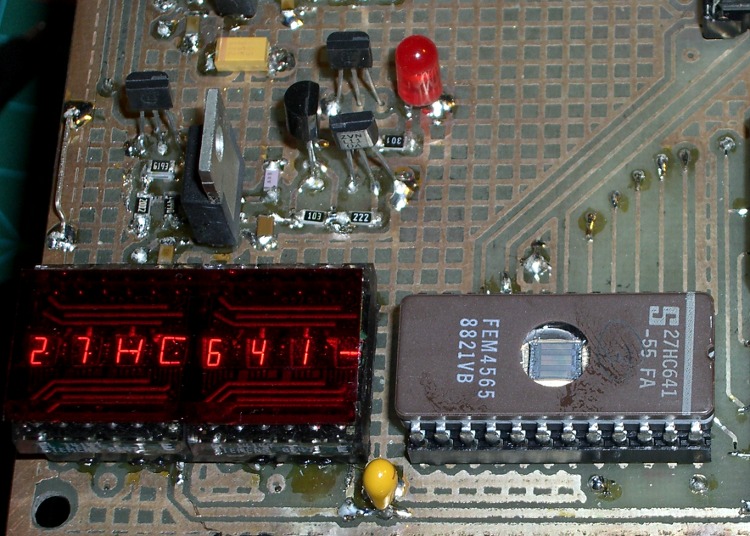
    The two displays are the dark-red rectangle in the lower-right of the first picture, covered with a snippet of the Primary Red filter described there.

    These closeups, without and with the filter, demonstrate why you really, really need a filter of some sort.

    DL1414 Unfiltered
    DL1414 Unfiltered

    DL1414 Filtered
    DL1414 Filtered

    Using the displays is straightforward, given the hardware-assisted SPI code from there. You could actually do it with just the I/O pins on an Arduino board, but you wouldn’t be able to do anything else. If you don’t have any other SPI registers, you could get away with a pair of HC595 outputs:  7 data + 2 address + 2 strobes + 5 outputs left over for something else.

    A few constants set the display size and a global buffer holds the characters:

    #define LED_SIZE            4            // chars per LED
    #define LED_DISPLAYS        2            // number of displays
    #define LED_CHARS           (LED_DISPLAYS * LED_SIZE)
    
    char LEDCharBuffer[LED_CHARS + 1];       // raw char buffer, can be used as a string
    

    A routine to exercise the LEDs by scrolling all 64 characters they can display goes a little something like this:

    Serial.println("Exercising LED display ...");
    
     Outbound.Controls |= CB_N_WRLED1_MASK | CB_N_WRLED0_MASK;        // set write strobes high
     digitalWrite(PIN_DISABLE_DO,LOW);                                // enable data outputs
    
     while (digitalRead(PIN_PB)) {
    
      digitalWrite(PIN_HEARTBEAT,HIGH);
    
      byte Character, Index;
    
      for (Character = 0x20; Character < 0x60; ++Character) {
       for (Index = 0; Index < LED_CHARS; ++Index) {
        LEDCharBuffer[Index] = Character + Index;
       }
       UpdateLEDs(LEDCharBuffer);
       delay(500);
    
       if (!digitalRead(PIN_PB)) {
        break;
       }
      }
    
      digitalWrite(PIN_HEARTBEAT,LOW);
     }
    
     WaitButtonUp();
    

    A routine to plop a string (up to 8 characters!) on the LEDs looks like this:

    void UpdateLEDs(char *pString) {
    byte Index = 0;
    
     while (*pString && (Index < LED_CHARS)) {
    
      Outbound.DataOut = *pString;           // low 6 bits used by displays
      Outbound.Address = ~Index;             // low 2 bits used by displays, invert direction
      Outbound.Controls &= ~(Index < LED_SIZE ? CB_N_WRLED1_MASK : CB_N_WRLED0_MASK);
    
      RunShiftRegister();
    
      digitalWrite(PIN_DISABLE_DO,LOW);      // show the data!
    
      Outbound.Controls |= CB_N_WRLED1_MASK | CB_N_WRLED0_MASK;
      RunShiftRegister();
    
      digitalWrite(PIN_DISABLE_DO,HIGH);     // release the buffers
    
      ++pString;
      ++Index;
     }


    You can use sprintf() to put whatever you like in that string:

    void ShowStatus(word Address,byte Data) {
    
     sprintf(LEDCharBuffer,"%04X  %02X",Address,Data);
     UpdateLEDs(LEDCharBuffer);
    
    }
    

    Not, of course, that anybody would actually use DL-1414 displays in this day & age, but the general idea might come in handy for something more, mmmm, elegant…

  • Tektronix 492 Spectrum Analyzer ROM and EPROM HEX Files

    Tek 492 Memory Board
    Tek 492 Memory Board

    Having gotten my buddy Eks back on the air with new EPROMs for his Tek 492 spectrum analyzer, here are the Tek 492 ROM Images (← that’s the link to the file!) you’ll need to fix yours.

    [Update: the comments for that post have pointers to other images and a clever hack to use a standard EPROM. If you’re not a stickler for perfection, that’s the way to go.]

    They’re taken from a “known good” Tek 492, so they should work fine: the firmware verifies the checksum in each chip as part of the startup tests; if it’s happy, we’re happy.

    Because WordPress doesn’t allow ZIP files, I tucked the HEX files into an OpenDocument file that also contains the pinouts and some interposer wiring hints & tips.

    If you’re using the OpenOffice.org word processor, you’re good to go. Open the document and get all the instructions you need to extract the files and put them to good use.

    If you’re not using OOo, then choose one of:

    • Install OpenOffice.org (it’s free software, so kwitcher bitchin’)
    • Futz with whatever Microsoft claims will import ODT files (if it doesn’t work, don’t blame me)
    • Just extract the HEX files and do whatever you want (if you know what you want)

    The trick, explained in the document itself, is that ODT files are just ZIP files with a different file extension, so any unzip program will unpack them. You won’t see the HEX files in the document, you must apply unzip to the ODT file itself.

    After unzipping, you’ll find three HEX files in the directory that originally held the ODT file, along with the collection of files that make up the OpenDocument document.

    The only files you care about:

    U1012 – 160-0886-04.hex
    U2023 – 160-0838-00.hex
    U2028 – 160-0839-00.hex

    Use ’em in good health…

    Oh, if you haven’t already figured it out, the DIP switch on your board is also bad. Saw the damn thing apart with a Dremel tool, pry off the debris, unsolder the pins, and install a new one. Just Do It.

  • Tektronix 492 Spectrum Analyzer Backplane Pin Spacing

    Tek 492 Memory Board
    Tek 492 Memory Board

    My buddy Eks asked me to help fix his new-to-him and guaranteed broken Tek 492 spectrum analyzer, which turned into a tour-de-force effort. One sub-project involved sucking the bits out of an existing “known-good” Tek memory card, which meant building a backplane connector and a circuit that behaved like a 6800 microcontroller… fortunately, it could be a lot slower.

    [Update: It seems searches involving “Tektronix 492” produce this page. You may also be interested in these posts…

    If those aren’t what you’re looking for, note that the correct spelling is “Tektronix“.

    Good luck fixing that gadget: it’s a great instrument when it works!]

    You can tell just by looking that this board was designed back in the day when PCB layout involved flexible adhesive tape traces and little sticky donut pads. Ground plane? We don’t need no stinkin’ ground plane!

    Actually, it’s a four-layer board done with the usual Tek attention to detail. They didn’t need a ground plane because they knew what they were doing. Remember, this is in a spectrum analyzer with an 18-GHz bandwidth and 80 dB dynamic range; a little digital hum and buzz just wouldn’t go unnoticed.

    Tek 492 Backplane Geometry
    Tek 492 Backplane Geometry

    Anyhow, the backplane pins are on a 0.150-inch grid within each block. The center block (pins 13-36) is 0.200 inches from the left block (pins 1-12) and 0.250 from the right block (pins 37-60).

    That means the left and right blocks are neatly aligned on the same 0.150-inch grid, with the middle block offset by 50 mils. You can’t plug the board in backwards unless you really work at it.

    Of course, Eks had some genuine gold-plated Tek pins in his stash: 24 mils square and 32 mils across the diagonal. They have 1/4″ clear above the crimped area that anchors them to the black plastic spacer and are 1/2″ tall overall. They’re not standard header pins, but I suspect you could use some newfangled pins in a pinch.

    Here’s what the reader board finally looked like, hacked traces and all, with the board connector to the rear. The memory board didn’t use all the backplane pins, so I only populated the ones that did something useful. The power-and-ground pins (left side of right pin block) stand separately from the other because I had to solder them to both the top and the bottom of the board: no plated-through holes!

    Tek 492 Memory Board Reader
    Tek 492 Memory Board Reader

    I cannot imagine this being useful to anybody else, but I defined an Eagle part for the connector so I could CNC-drill the board. Drop me a note and I’ll send it to you.

    [Update: this turned into a Circuit Cellar column, so you can fetch a ZIP file from their FTP site that has all manner of useful stuff.]

    Memo to Self: The drill size follows the pin’s diagonal measurement… not the side! Duh.

  • Useful Hex and Binary File Utilities

    I’m doing some work with a one-off ROM reader & EPROM programmer, so it’s once again time to mess around with Intel HEX files, raw binary images, and the like.

    The key routine (which runs on an Arduino Decimila) to dump a ROM in HEX format goes like this, with all the constants & variables & functions doing the obvious things:

    void DumpHC641(void) {
    
    word Address,Offset;
    byte DataRd,Checksum;
    
     for (Address = 0; Address < ROM_SIZE; Address += IHEX_BYTES) {
      sprintf(PrintBuffer,":%02X%04X00",IHEX_BYTES,(word)Address);           // emit line header
      Serial.print(PrintBuffer);
      Checksum = IHEX_BYTES + lowByte(Address) + highByte(Address) + 0x00;   // record type 0x00
      for (Offset = 0; Offset < IHEX_BYTES; ++Offset) {
       digitalWrite(PIN_HEARTBEAT,HIGH);
       DataRd = ReadHC641(Address + Offset);
       digitalWrite(PIN_HEARTBEAT,LOW);
       Checksum += DataRd;
       sprintf(PrintBuffer,"%02X",DataRd);                                   // data byte
       Serial.print(PrintBuffer);
      }
      Checksum = -Checksum;                                                  // two's complement
      sprintf(PrintBuffer,"%02X",Checksum);
      Serial.println(PrintBuffer);
     }
     Serial.println(":00000001FF");                                          // emit end-of-file line
    }
    

    So getting an Intel HEX file is just a matter of capturing the serial output, whacking off any debris on either side of the main event, and saving it.

    The srec_cat program handles conversions among a myriad formats, most of which I can’t even pronounce. The few I use go a little something like this:

    srec_cat mumble.hex -intel -o mumble.bin -binary
    srec_cat mumble.bin -binary -o mumble.hex -intel
    srec_cat mumble.bin -binary -o mumble.txt -hex_dump
    srec_cat -generate 0x0000 0x2000 -constant 0x00 -o mumble.txt -intel
    

    It’s sometimes handy to apply srec_cat to a group of similarly suffixed files, in which case some Bash string chopping comes in handy. For example, to convert some hex files into binary:

    for f in 27HC641*hex ; do echo ${f%%hex} ; srec_cat "$f"  -intel -o "${f%%hex}"bin -binary ; done
    

    Good old diff works fine on text files, but in this case it’s better to see which bytes have changed, rather than which lines (which don’t apply in the context of a binary file). The vbindiff program looks great on a portrait-mode display.

    I don’t do much binary editing, but tweak serves my simple needs. Confusingly, members of this class of program are called “hex editors”, but they really work on binary files.

    There’s also diff3, for those rare cases where you must mutually compare three text files. Makes my head spin every time…

    All those programs are likely packages in your favorite Linux distro.