Another pass at my Logitech Dual-Action Gamepad used as an EMC2 control pendant, but this time using an Eagle ULP (User Language Program) that converts a schematic into EMC2 HAL code.
I tweaked Martin Schöneck’s original ULP a bit, added (some of the) new devices found in EMC2.4, added the corresponding Eagle symbols & devices to the library, then drew up a schematic based on my hand-hewn HAL code with some improvements. Ran the script and shazam the HAL code worked just fine (after a bit of debugging the infrastructure, of course).
The new ULP and library are not quite ready for prime time, but this is a stick in the ground to mark some progress. You can certainly use the HAL code directly, without fiddling around in the schematic: stuff the whole program (at the end of the post) in your existing (but likely empty) custom_postgui.hal file.
The schematic is, of course, much fluffier than the corresponding code, particularly because I chopped it into five easily printed pages. Here’s the Big Picture overview of what’s going on in each page; click the pix for bigger images.
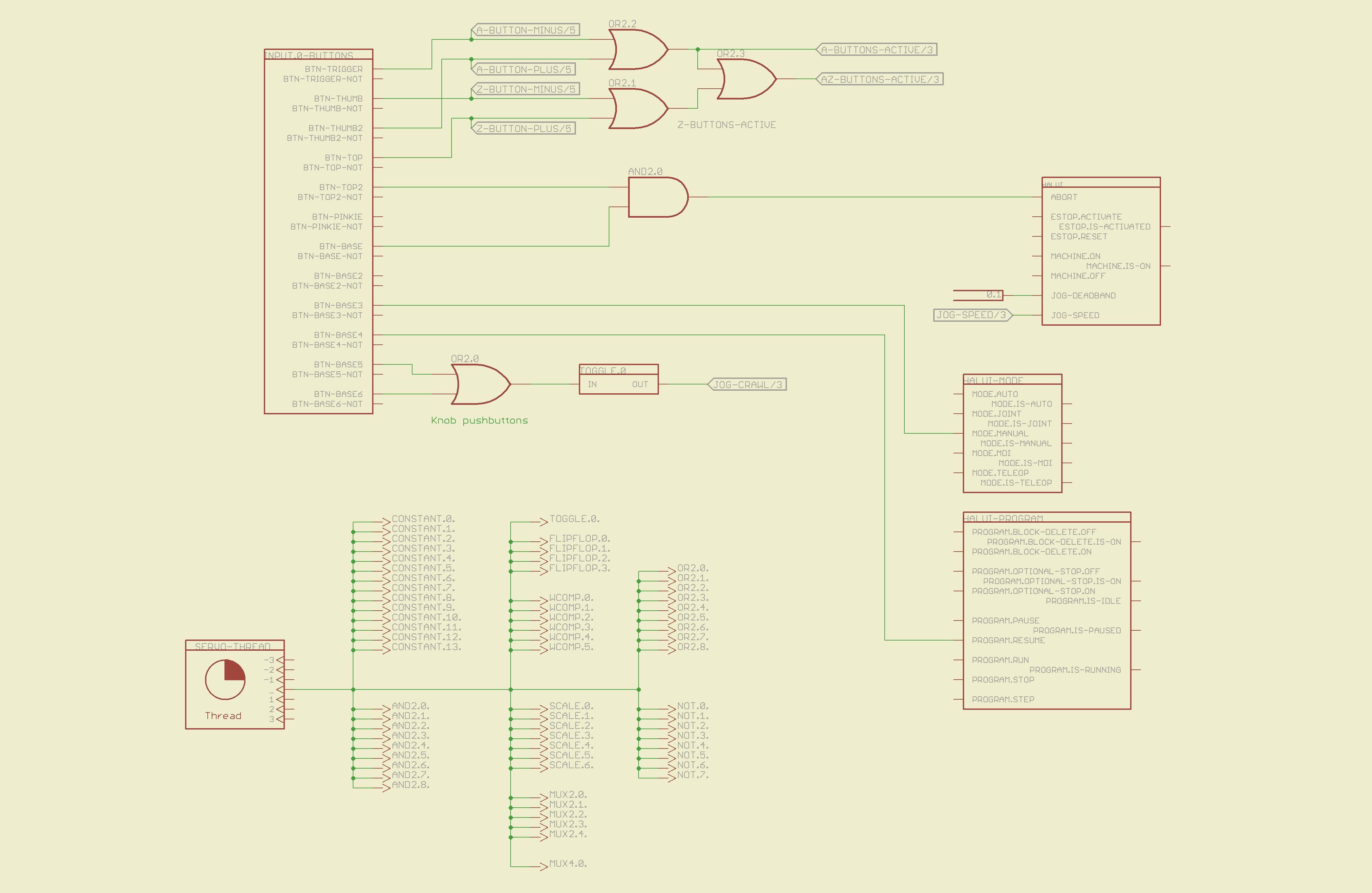
The servo thread interface device in the lower left provides the halui timing. The big block in the upper left has all the Logitech gamepad buttons, including the four big ones used for Z and A axis jogging. I changed the two left-rear buttons to activate the Abort signal rather than Estop, not that I use them all that much anyway.
The two joystick knobs have pushbuttons, which I combine and use to toggle a flipflop that will select the jogging speed: fast or crawl.
I also cut the jog deadband from 0.2 to 0.1, which makes the joysticks much more responsive.
The big block on the left has all the gamepad’s analog axes. The HAT0X and HAT0Y axes correspond to the top-hat pushbuttons; they’re not really analog at all, although they take on -1.0 / 0.0 / + 1.0 floating point values. The window comparators determine which joystick axes are active, which comes in handy later on.

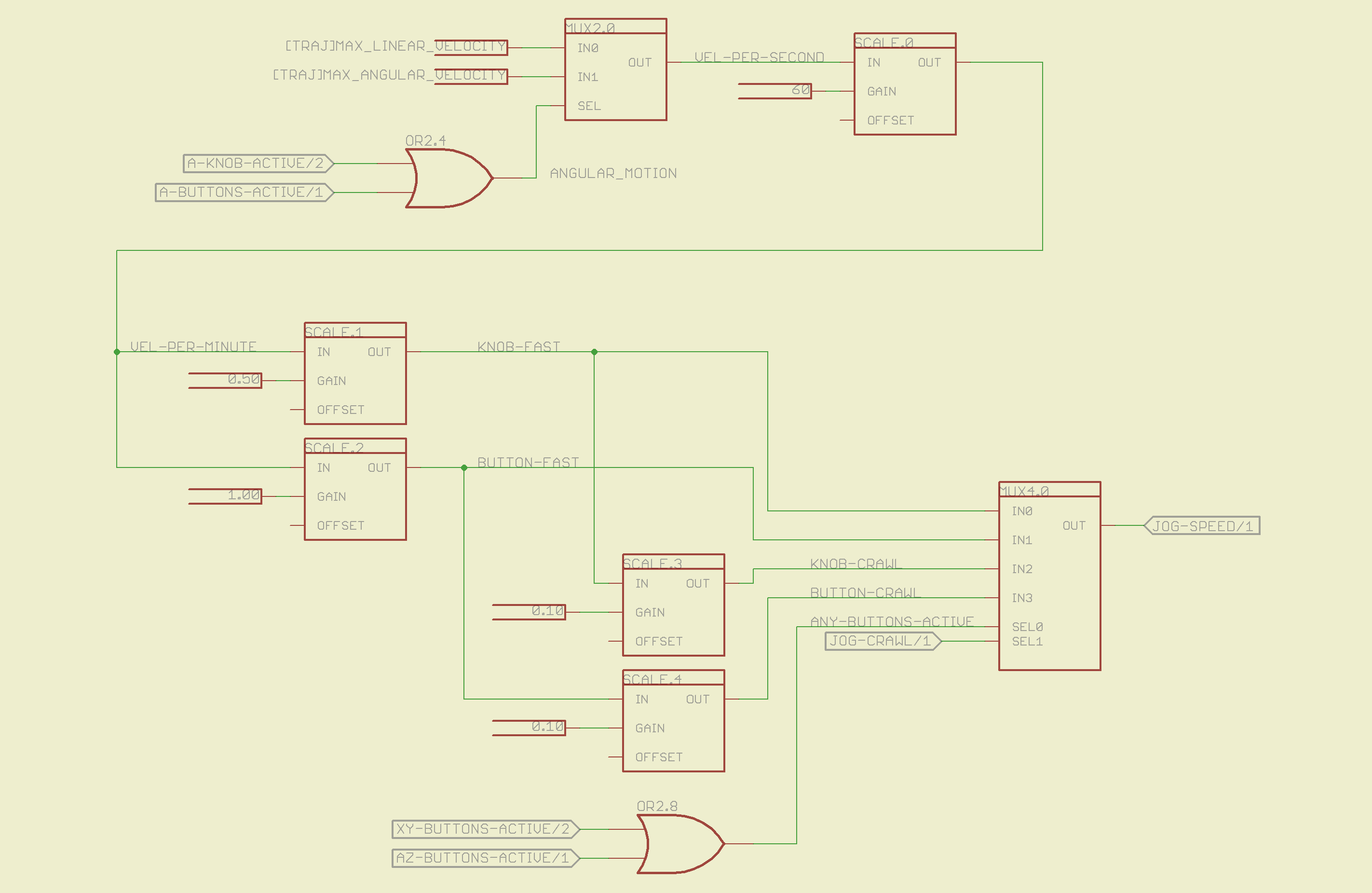
The HAL jogging control has a single input that sets the default speed, but the proper value is vastly different depending on whether you’re jogging with linear or angular motion. This page picks out which ini file MAX_VELOCITY value to use, converts from units/sec to units/min, then does Cool Thing #1: scales the speed so that the fast/crawl speeds work out nicely.
I use the buttons to jog rapidly from here to there, then creep up on the alignment point using the joysticks. Pressing the joysticks downward switches from Fast to Crawl speeds, which provides sort of a gearshift that’s useful for coarse / fine adjustments.
The buttons run at two speeds:
- Fast: the maximum speed for the axis
- Crawl: 10% of that value
The joysticks have a lower top speed:
- Fast: half the maximum speed of the axis
- Crawl: 10% of that value
All those values go into the mux4 block and thence to the HAL jog speed control.
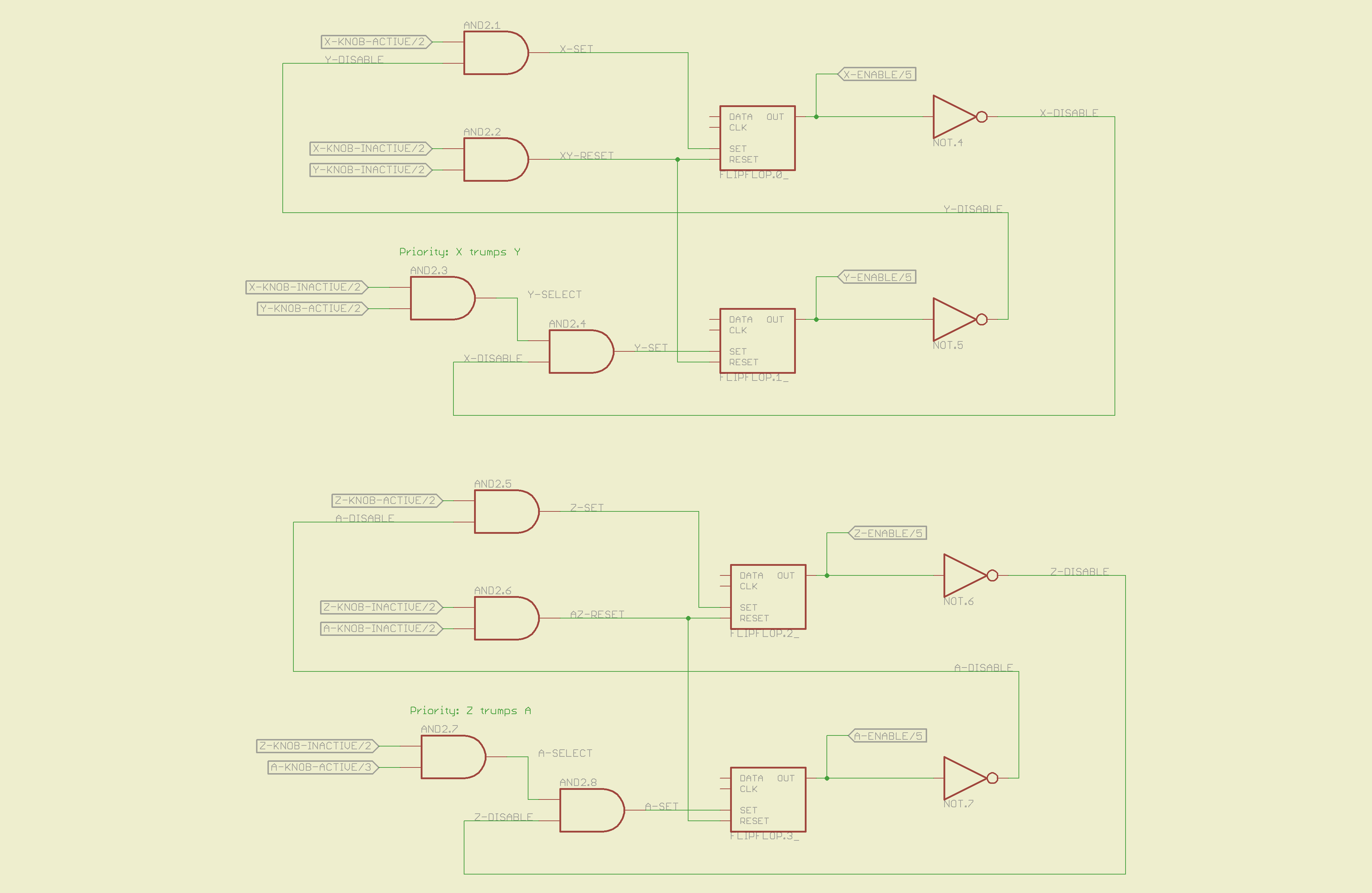
This page does Cool Thing #2: prioritize the joystick axes and lock out the one that started moving last. The general idea is that it’s painfully easy to move the joysticks diagonally, which is great for gaming and terrible for milling machine control. A pair of flipflops for each joystick remember which axis started moving first.
If you want to move diagonally, just press the buttons; they’re not locked out, so you can do what you want.
The motion comes together on the last page, where scale blocks flip the direction of the Y and Z joystick axes so positive motion is upward. The multiplexers allow only the active axis of each joystick to reach the HAL analog jog inputs; you can vary the speed of that axis up to the maximum as you’d expect. The buttons drive the digital inputs that jog at that maximum speed; the Y and Z button directions get sorted out appropriately.
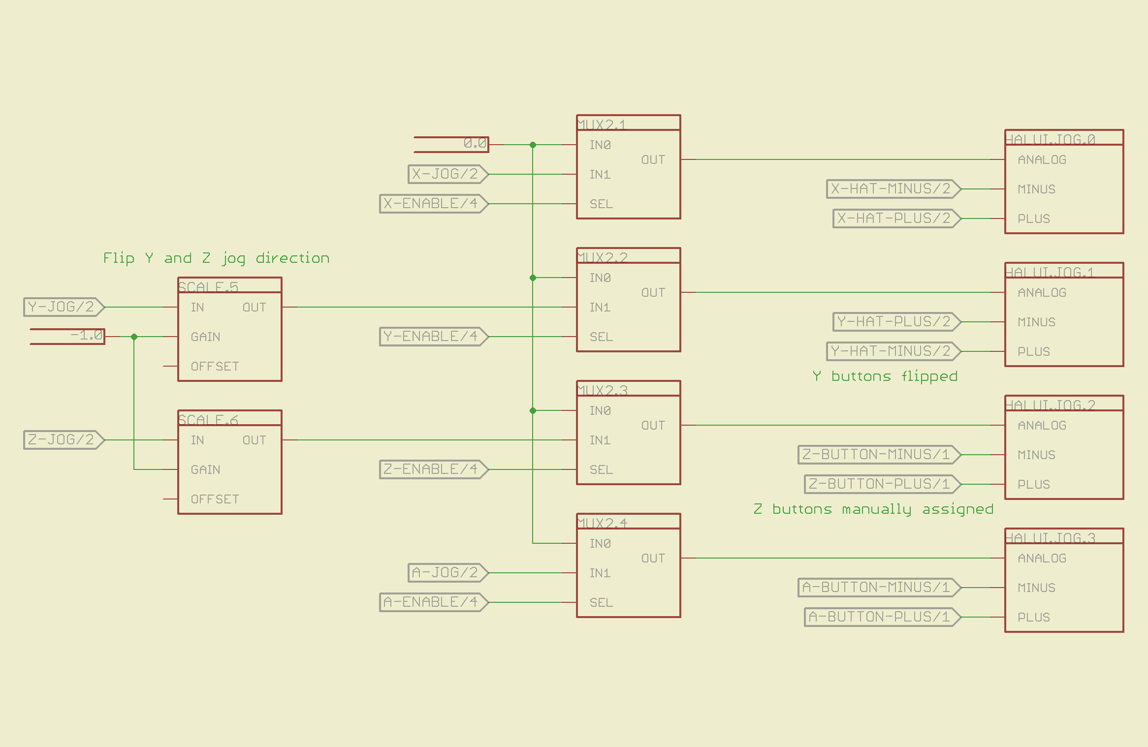
Those five pages boil down into the following code, which I manually insert into my custom_postgui.hal file, along with the tool length probe pin definition.
# HAL config file automatically generated by Eagle-CAD hal-write.ulp
# (C) Martin Schoeneck.de 2008
# Mods Ed Nisley 2010

# Path: [/mnt/bulkdata/Project Files/eagle/projects/EMC2 HAL Configuration/]
# ProjectName: [Logitech Gamepad]
# File name: [/mnt/bulkdata/Project Files/eagle/projects/EMC2 HAL Configuration/Logitech Gamepad.hal]

####################################################
# Load realtime and userspace modules
loadrt constant	count=14
loadrt and2	count=9
loadrt flipflop	count=4
loadrt mux2	count=5
loadrt mux4	count=1
loadrt not	count=8
loadrt or2	count=9
loadrt scale	count=7
loadrt toggle	count=1
loadrt wcomp	count=6

####################################################
# Hook functions into threads
addf toggle.0	servo-thread
addf wcomp.1	servo-thread
addf wcomp.2	servo-thread
addf wcomp.3	servo-thread
addf and2.0	servo-thread
addf and2.4	servo-thread
addf and2.3	servo-thread
addf and2.2	servo-thread
addf and2.1	servo-thread
addf constant.6	servo-thread
addf constant.5	servo-thread
addf constant.4	servo-thread
addf constant.3	servo-thread
addf constant.2	servo-thread
addf constant.1	servo-thread
addf constant.0	servo-thread
addf constant.7	servo-thread
addf constant.8	servo-thread
addf scale.1	servo-thread
addf scale.2	servo-thread
addf scale.3	servo-thread
addf mux4.0	servo-thread
addf mux2.0	servo-thread
addf scale.4	servo-thread
addf scale.0	servo-thread
addf wcomp.5	servo-thread
addf wcomp.4	servo-thread
addf wcomp.0	servo-thread
addf flipflop.1	servo-thread
addf flipflop.0	servo-thread
addf and2.5	servo-thread
addf and2.6	servo-thread
addf and2.7	servo-thread
addf and2.8	servo-thread
addf flipflop.2	servo-thread
addf flipflop.3	servo-thread
addf or2.4	servo-thread
addf or2.8	servo-thread
addf or2.7	servo-thread
addf or2.6	servo-thread
addf or2.5	servo-thread
addf or2.3	servo-thread
addf or2.2	servo-thread
addf or2.1	servo-thread
addf or2.0	servo-thread
addf not.1	servo-thread
addf not.2	servo-thread
addf not.3	servo-thread
addf not.4	servo-thread
addf not.5	servo-thread
addf not.6	servo-thread
addf not.7	servo-thread
addf not.0	servo-thread
addf constant.9	servo-thread
addf mux2.1	servo-thread
addf mux2.2	servo-thread
addf mux2.3	servo-thread
addf mux2.4	servo-thread
addf constant.10	servo-thread
addf constant.11	servo-thread
addf scale.5	servo-thread
addf scale.6	servo-thread
addf constant.12	servo-thread
addf constant.13	servo-thread

####################################################
# Set parameters

####################################################
# Set constants
setp constant.0.value	+0.02
setp constant.1.value	-0.02
setp constant.2.value	60
setp constant.3.value	1.00
setp constant.4.value	0.10
setp constant.5.value	0.50
setp constant.6.value	0.10
setp constant.7.value	+0.5
setp constant.8.value	-0.5
setp constant.9.value	0.0
setp constant.10.value	[TRAJ]MAX_LINEAR_VELOCITY
setp constant.11.value	[TRAJ]MAX_ANGULAR_VELOCITY
setp constant.12.value	-1.0
setp constant.13.value	0.1

####################################################
# Connect Modules with nets
net a-button-minus input.0.btn-trigger or2.2.in0 halui.jog.3.minus
net a-button-plus input.0.btn-thumb2 or2.2.in1 halui.jog.3.plus
net a-buttons-active or2.2.out or2.3.in0 or2.4.in1
net a-disable not.7.out and2.5.in1
net a-enable flipflop.3.out not.7.in mux2.4.sel
net a-jog wcomp.2.in input.0.abs-z-position mux2.4.in1
net a-knob-active not.2.out or2.4.in0 and2.7.in1
net a-knob-inactive wcomp.2.out not.2.in and2.6.in1
net a-select and2.8.in0 and2.7.out
net a-set flipflop.3.set and2.8.out
net angular_motion or2.4.out mux2.0.sel
net any-buttons-active mux4.0.sel0 or2.8.out
net az-buttons-active or2.3.out or2.8.in1
net az-reset flipflop.2.reset and2.6.out flipflop.3.reset
net button-crawl scale.4.out mux4.0.in3
net button-fast scale.2.out mux4.0.in1 scale.4.in
net jog-crawl toggle.0.out mux4.0.sel1
net jog-speed halui.jog-speed mux4.0.out
net knob-crawl mux4.0.in2 scale.3.out
net knob-fast mux4.0.in0 scale.1.out scale.3.in
net n_1 constant.10.out mux2.0.in0
net n_2 and2.0.in0 input.0.btn-top2
net n_3 and2.0.in1 input.0.btn-base
net n_4 and2.0.out halui.abort
net n_5 halui.mode.manual input.0.btn-base3
net n_6 wcomp.0.max wcomp.1.max wcomp.2.max wcomp.3.max constant.0.out
net n_7 halui.program.resume input.0.btn-base4
net n_8 wcomp.0.min wcomp.1.min wcomp.2.min wcomp.3.min constant.1.out
net n_9 mux2.0.in1 constant.11.out
net n_10 constant.12.out scale.5.gain scale.6.gain
net n_11 input.0.btn-base5 or2.0.in0
net n_12 input.0.btn-base6 or2.0.in1
net n_13 constant.9.out mux2.1.in0 mux2.2.in0 mux2.3.in0 mux2.4.in0
net n_14 mux2.1.out halui.jog.0.analog
net n_15 toggle.0.in or2.0.out
net n_16 constant.2.out scale.0.gain
net n_17 constant.5.out scale.1.gain
net n_18 constant.3.out scale.2.gain
net n_19 constant.4.out scale.3.gain
net n_20 scale.4.gain constant.6.out
net n_21 halui.jog.1.analog mux2.2.out
net n_22 mux2.2.in1 scale.5.out
net n_23 scale.6.out mux2.3.in1
net n_24 constant.13.out halui.jog-deadband
net n_25 wcomp.4.max constant.7.out wcomp.5.max
net n_26 constant.8.out wcomp.4.min wcomp.5.min
net n_27 mux2.3.out halui.jog.2.analog
net n_28 halui.jog.3.analog mux2.4.out
net vel-per-minute scale.0.out scale.1.in scale.2.in
net vel-per-second mux2.0.out scale.0.in
net x-buttons-active or2.7.in0 or2.5.out
net x-disable not.4.out and2.4.in1
net x-enable not.4.in flipflop.0.out mux2.1.sel
net x-hat-jog wcomp.4.in input.0.abs-hat0x-position
net x-hat-minus wcomp.4.under or2.5.in1 halui.jog.0.minus
net x-hat-plus or2.5.in0 wcomp.4.over halui.jog.0.plus
net x-jog wcomp.0.in input.0.abs-x-position mux2.1.in1
net x-knob-active not.0.out and2.1.in0
net x-knob-inactive wcomp.0.out not.0.in and2.2.in0 and2.3.in0
net x-set and2.1.out flipflop.0.set
net xy-buttons-active or2.7.out or2.8.in0
net xy-reset flipflop.0.reset and2.2.out flipflop.1.reset
net y-buttons-active or2.6.out or2.7.in1
net y-disable not.5.out and2.1.in1
net y-enable flipflop.1.out not.5.in mux2.2.sel
net y-hat-jog input.0.abs-hat0y-position wcomp.5.in
net y-hat-minus wcomp.5.under or2.6.in1 halui.jog.1.plus
net y-hat-plus or2.6.in0 wcomp.5.over halui.jog.1.minus
net y-jog wcomp.1.in input.0.abs-y-position scale.5.in
net y-knob-active not.1.out and2.3.in1
net y-knob-inactive not.1.in wcomp.1.out and2.2.in1
net y-select and2.4.in0 and2.3.out
net y-set flipflop.1.set and2.4.out
net z-button-minus input.0.btn-thumb or2.1.in0 halui.jog.2.minus
net z-button-plus input.0.btn-top or2.1.in1 halui.jog.2.plus
net z-buttons-active or2.1.out or2.3.in1
net z-disable not.6.out and2.8.in1
net z-enable not.6.in flipflop.2.out mux2.3.sel
net z-jog wcomp.3.in input.0.abs-rz-position scale.6.in
net z-knob-active not.3.out and2.5.in0
net z-knob-inactive not.3.in wcomp.3.out and2.7.in0 and2.6.in0
net z-set and2.5.out flipflop.2.set
The ULP script that eats the schematic and poots out the HAL code:
/******************************************************************************
 * HAL-Configurator
 *
 * Author: Martin Schoeneck 2008
 * Additional gates & tweaks: Ed Nisley KE4ZNU 2010
 *****************************************************************************/
#usage "<h1>HAL-Configurator</h1>Start from a Schematic where symbols from hal-config.lbr are used!";

string output_path =    "./";
string dev_loadrt =     "LOADRT";
string dev_loadusr =    "LOADUSR";
string dev_thread =     "THREAD";
string dev_parameter =  "PARAMETER";

string dev_names[] = {
"CONSTANT",								// must be first entry to make set_constants() work
"ABS",				// 2.4
"AND2",
"BLEND",			// 2.4
"CHARGE-PUMP",		// 2.4
"COMP",
"CONV_S32_FLOAT",	// 2.4
"DDT",				// 2.4
"DEADZONE",			// 2.4
"DEBOUNCE",			// 2.4
"EDGE",
"ENCODER",			// 2.4
"ENCODER-RATIO",	// 2.4
"ESTOP-LATCH",
"FLIPFLOP",
"FREQGEN",			// 2.4
"LOWPASS",
"MULT2",			// 2.4
"MUX2",
"MUX4",				// 2.4
"MUX8",				// 2.4
"NEAR",				// 2.4
"NOT",
"ONESHOT",
"OR2",
"SAMPLER",			// 2.4
"SCALE",			// 2.4
"SELECT8",			// 2.4
"SUM2",
"TIMEDELAY",		// 2.4
"TOGGLE",			// 2.4
"WCOMP",			// 2.4
"XOR2",				// 2.4
""					// end flag
};

string init = "# HAL config file automatically generated by Eagle-CAD hal-write.ulp\n# (C) Martin Schoeneck.de 2008\n# Mods Ed Nisley 2010\n";

/*******************************************************************************
 * Global Stuff
 ******************************************************************************/

string FileName;
string ProjectPath;
string ProjectName;

void Info(string Message) {
	dlgMessageBox(";<b>Info</b><p>\n" + Message);
}

void Warn(string Message) {
	dlgMessageBox("!<b>Warning</b><p>\n" + Message + "<p>see usage");
}

void Error(string Message) {
	dlgMessageBox(":<hr><b>Error</b><p>\n" + Message + "<p>see usage");
	exit(1);
}

string replace(string str, char a, char b) {
	// in string str replace a with b
	int pos = -1;
	do {
		// find that character
		pos = strchr(str, a);
		// replace if found
		if(pos >= 0) {
			str[pos] = b;
		}
	} while(pos >= 0);

	return str;
}

// the part name contains an index and is written in capital letters
string get_module_name(UL_PART P) {
	// check module name, syntax: INDEX:NAME
	string mod_name = strlwr(P.name);
	// split string at the : if exists
	string a[];
	int c = strsplit(a, mod_name, ':');
	mod_name = a[c-1];
	// if name starts with '[' we need uppercase letters
	if(mod_name[0] == '[') {
		mod_name = strupr(mod_name);
	}

	return mod_name;
}

string comment(string mess) {
	string str = "\n\n####################################################\n";
	if(mess != "") {
		str += "# " + mess + "\n";
	}

	return str;
}

// if this is a device for loading a module, load it (usr/rt)
string load_module(UL_PART P) {
	string str = "";

	// it's a module if the device's name starts with LOADRT/LOADUSR
	if((strstr(P.device.name, dev_loadrt) == 0) ||
	   (strstr(P.device.name, dev_loadusr) == 0)) {

		// now add the string to our script
		str += P.value + "\n";
	}

	return str;
}

// count used digital gates (and, or, etc) and load module if neccessary
string load_blocks() {
	string str = "";

	int index;

	int dev_counters[];
	string dname[];

	// count the gates that are used
	schematic(S) { S.parts(P) {
		strsplit(dname,P.device.name,'.');		// extract first part of name
		if ("" != lookup(dev_names,dname[0],0)) {
			for (index = 0;  (dname[0] != dev_names[index]) ; index++) {
				continue;
			}
			dev_counters[index]++;
		}
	} }

// force lowercase module names...

	for (index = 0; ("" != dev_names[index]) ; index++) {
		if (dev_counters[index]) {
			sprintf(str,"%sloadrt %s\tcount=%d\n",str,strlwr(dev_names[index]),dev_counters[index]);
		}
	}

	return str;
}

string hook_function(UL_NET N) {
	string str = "";

	// is this net connected to a thread (work as functions here)?
	int    noclkpins       = 0;
	string thread_name     = "";  // this net should be connected to a thread
	string thread_position = "";
	N.pinrefs(PR) {
		// this net is connected to a clk-pin
		if(PR.pin.function == PIN_FUNCTION_FLAG_CLK) {
			// check the part: is it a thread-device?
			if(strstr(PR.part.device.name, dev_thread) == 0) {
				// we need the name of the thread
				thread_name = strlwr(PR.part.name);
				// and we need the position (position _ is ignored)
				thread_position = strlwr(PR.pin.name);
				thread_position = replace(thread_position, '_', ' ');
			}
		} else {
			// no clk-pin, this is no function-net
			noclkpins++;
			break;
		}
	}

	// found a thread?
	if(noclkpins == 0 && thread_name != "") {
		// all the other pins are interesting now
		N.pinrefs(PR) {
			// this pin does not belong to the thread
			if(strstr(PR.part.device.name, dev_thread) != 0) {
				// name of the pin is name of the function
				//string function_name = strlwr(PR.pin.name);
				string function_name = strlwr(PR.instance.gate.name);
				// if functionname starts with a '.', it will be appended to the modulename
				if(function_name[0] == '.') {
					// if the name is only a point, it will be ignored
					if(strlen(function_name) == 1) {
						function_name = "";
					}
					function_name = get_module_name(PR.part) + function_name;
				}
				str += "addf " + function_name + "\t" + thread_name + "\t" + thread_position + "\n";
			}
		}
	}

	return str;
}

string set_parameter(UL_NET N) {
	string str = "";

	// is this net connected to a parameter-device?
	int    nodotpins       = 0;
	string parameter_value = "";
	N.pinrefs(PR) {
		// this net is connected to a dot-pin
		if(PR.pin.function == PIN_FUNCTION_FLAG_DOT) {
			// check the part: is it a parameter-device?
//			str += "** dev name [" + PR.part.device.name + "] [" + dev_parameter + "]\n";
			if(strstr(PR.part.device.name, dev_parameter) == 0) {
				// we need the value of that parameter
				parameter_value = PR.part.value;
//				str += "**  value [" + PR.part.value +"]\n";
			}
		} else {
			// no clk-pin, this is no function-net
			nodotpins++;
			break;
		}
	}

	// found a parameter?
	if(nodotpins == 0 && parameter_value != "") {
		// all the other pins are interesting now
		N.pinrefs(PR) {
//			str += "** dev name [" + PR.part.device.name + "] [" + dev_parameter + "]\n";
			// this pin does not belong to the parameter-device
			if(strstr(PR.part.device.name, dev_parameter) != 0) {
				// name of the pin is name of the function
				//string parameter_name = strlwr(PR.pin.name);
				string parameter_name = strlwr(PR.instance.gate.name);
				// if functionname starts with a '.', it will be appended to the modulename
//				str += "** param (gate) name [" + parameter_name + "]\n";
				if(parameter_name[0] == '.') {
					// if the name is only a point, it will be ignored
					if(strlen(parameter_name) == 1) {
						parameter_name = "";
					}
					parameter_name = get_module_name(PR.part) + parameter_name;
//					str += "** param (part) name [" + parameter_name + "]\n";
				}
				str += "setp " + parameter_name + "\t" + parameter_value + "\n";
			}
		}
	}

	return str;
}

// if this is a 'constant'-device, set its value
// NOTE: this is hardcoded to use the first entry in the dev_names[] array!
string set_constants(UL_PART P) {
	string str = "";

	// 'constant'-device?
	if(strstr(P.device.name, dev_names[0]) == 0) {
		str += "setp " + get_module_name(P) + ".value\t" + P.value + "\n";
	}

	return str;
}

string connect_net(UL_NET N) {
	string str = "";

	// find all neccessary net-members
	string pins = "";
	N.pinrefs(P) {
		// only non-functional pins are connected
		if(P.pin.function == PIN_FUNCTION_FLAG_NONE) {
			string pin_name =  strlwr(P.pin.name);
			string part_name = strlwr(P.part.name);
			pin_name =  replace(pin_name,  '$', '_');
			part_name = replace(part_name, '$', '_');
			pins += part_name + "." + pin_name + " ";
		}
	}

	if(pins != "") {
		string net_name = strlwr(N.name);
		net_name = replace(net_name, '$', '_');
		str += "net " + net_name + " " + pins + "\n";
	}

	return str;
}

/*******************************************************************************
 * Main program.
 ******************************************************************************/
// is the schematic editor running?
if (!schematic) {
	Error("No Schematic!<br>This program will only work in the schematic editor.");
}

schematic(S) {
	ProjectPath = filedir(S.name);
	ProjectName = filesetext(filename(S.name), "");
}

// build configuration
string cs = init + "\n\n";

FileName = ProjectPath + ProjectName + ".hal";

cs += "# Path: [" + ProjectPath + "]\n";
cs += "# ProjectName: [" + ProjectName + "]\n";
//cs += "# File name: [" + FileName + "]\n\n";

// ask for a filename: where should we write the configuration?

FileName = dlgFileSave("Save Configuration", FileName, "*.hal");

if(!FileName) {
	exit(0);
}

cs += "# File name: [" + FileName + "]\n\n";

schematic(S) {
	// load modules
	cs += comment("Load realtime and userspace modules");
	S.parts(P) {
		cs += load_module(P);
	}

	// load blocks
	cs += load_blocks();

	// add functions
	cs += comment("Hook functions into threads");
	S.nets(N) {
		cs += hook_function(N);
	}

	// set parameters
	cs += comment("Set parameters");
	S.nets(N) {
		cs += set_parameter(N);
	}

	// set constant values
	cs += comment("Set constants");
	S.parts(P) {
		cs += set_constants(P);
	}

	// build nets and connect them
	cs += comment("Connect Modules with nets");
	S.nets(N) {
		cs += connect_net(N);
	}
}

// open/overwrite the target file to save the configuration
output(FileName, "wt") {
	printf(cs);
}
Most of that script is Martin’s work; I just cleaned it up. You can download it by hovering over the code to make the little toolbar pop up near the upper-right corner of the text, then:
- click a little button to copy it to the clipboard or
- click another little button to view the source, then save that file
You’ll also need the Eagle library that goes along with the script, but WordPress doesn’t like .lbr files. Here’s the hal-config-2.4.lbr file with a totally bogus odt extension. Download it, rename it to remove the .odt extension, and it’s all good.
There is basically no documentation for any of this. I figured out what to do by looking at the source and Martin’s sample schematic, but now you have two sample schematics: the situation is definitely improving!