The Smell of Molten Projects in the Morning

Ed Nisley's Blog: Shop notes, electronics, firmware, machinery, 3D printing, laser cuttery, and curiosities. Contents: 100% human thinking, 0% AI slop.

Category: Electronics Workbench

Electrical & Electronic gadgets

  • Cartridge Heaters: Mounting Blocks

    Drilling SHCS head clearance
    Drilling SHCS head clearance

    MBI sent me a selection of 1/4-inch cartridge heaters to evaluate, seeing as how I’ve been such a pest on the subject of those poor aluminum-case power resistor heaters. Thanks, Zach!

    I initially thought I could punch the cores out of the resistors and slip the cartridge heaters into the holes, but it turns out the resistor bodies aren’t quite the right size: slightly too short with slightly too large holes. So it goes. Some earlier thoughts live there.

    This is a first pass at building mounting blocks to attach cartridge heaters to a stock MK5 Thermal Core. Ideally, you want a solid Thermal Core with a hole or two for the heaters next to the filament extrusion nozzle, but that requires fancier machining that I’m ready for right now. The fabled nophead shows how that looks for a ceramic power resistor.

    The obvious question is whether you want a single high-wattage cartridge heater or a pair of low(er)-wattage units. I think a core-with-hole can get away with a single heater, which is also the lower-cost option. My thermal measurements suggest the Core is pretty much isothermal, so there’s no problem with distributing the heat evenly from one side to the other.

    However, adding two lower-wattage heaters to a stock MK5 Thermal Core makes more sense, because the interface between the blocks and the Core seems to run a bit under 1 °C/W. A single 40 W heater would thus run 30-40 °C higher than the Core: call it 260 °C. IMO, that’s much too high for something an inch away from a plywood frame and an acrylic support structure.

    A pair of 25 W heaters would run at 245 °C-ish. That’s still pretty hot, but every little bit helps. I’ll start with that arrangement and see how it works.

    Block top and bottom
    Block top and bottom

    The blocks are ordinary steel from the Scrap Box: a convenient length of 1×1-inch bar stock that somebody else had made into something else a long time ago. I bandsawed off four 1×1-inch slabs, each about 5/8″ thick. A second bandsaw cut turned the square slabs into rectangles. I finished two blocks; the other two slabs await more experience with how these work.

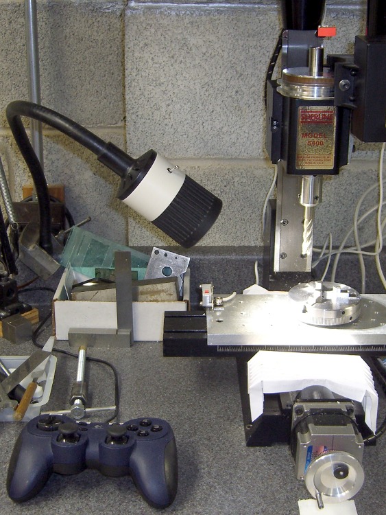
    I squared up the blocks with a flycutter in the Sherline, then sanded down the bottom surface a bit. The thermal tests suggest the contact is Good Enough with a reasonably flat surface, so I settled for a used-car finish: high shine and deep scratches. They’re actually smoother than the pictures would have you believe.

    The Thermal Core has hard inch dimensions (minus cleanup cuts): 1 inch front-to-back and 13/16 inch tall. I generally work in metric, so the sketch at the bottom has everything in millimeters.

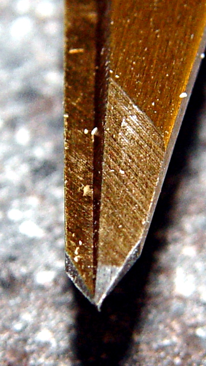
    The mounting blocks have holes matching the resistor footprint. I drilled clearance holes for the heads of the original M2 socket head cap screws, ran an end mill down the hole to flatten the bottom, then drilled clearance holes for the threads. Those holes are perilously close to the edge, but the blocks really don’t want to be any taller. Perhaps use a less-generous clearance?

    The alternative would be to mill a flange along the edge to match the resistor mounts and put the SHCS heads in free air, but that seemed like more work and it would cramp the thermal path from cartridge to block.

    I also thought about chamfering the edges to make the blocks look less, well, blocky, but that’s in the nature of fine tuning.

    The cartridge heaters slip-fit into a nominal 0.250 hole; the samples are 0.247 to 0.248 and (from what I read) the diameter tolerance stays on the minus side of 0.250. I don’t have a 0.250 reamer, which is how you get a precise hole ID, so I’ll go with drilled holes. Fortunately, I have a set of letter-size drills in nearly new condition:

    • A drill = 0.234 to poke a hole in the block
    • E drill = 0.250 to get the final diameter

    The final holes worked out to be exactly 0.250 inch, to the limits of my measurement ability, which I will declare to be Good Enough. The cartridges have a loose slip fit with no side-to-side play.

    The cartridges expand when heated and squeeze against the hole to make good thermal contact. While cool, however, they can slide out without much urging, so I added a 4-40 setscrew. It’s on the butt end of the cartridge heater shell, away from the leads, so if a cartridge becomes one with the block I can drive it out with a pin punch. Putting the setscrew at the end with the wire leads makes more sense (it’s cooler there), but then you’d be beating the entire length of the cartridge out past the setscrew hole.

    The setscrew and the M2 SHCSs get a liberal dose of anti-seize grease before assembly.

    Here’s what the holders looked like, just before bolting them in place:

    Cartridge heaters in blocks
    Cartridge heaters in blocks

    Doodles with the more-or-less as-built dimensions:

    Heater block dimensions
    Heater block dimensions
  • Thing-O-Matic: Platform Light

    Platform light overview
    Platform light overview

    The inside of a Thing-O-Matic gets pretty dark, particularly with the Lazy Susan spool parked on top, so I added a spot light to the Z stage.

    The alternative seems to be LED strip lighting all over the inside, but my Parts Heap doesn’t have any of those yet and it did have a 10 mm white LED. The thing runs at 100 mA, so a 15 Ω 1/2 W resistor (to a +5V tap), a few snippets of heat-shrink tubing, and a blob of hot-melt glue did the trick.

    Some sculpture armature wire that’s been kicking around for years holds the LED (wrap it around, add hot-melt glue) and doesn’t mind the occasional bump. I crimped the wire in a solderless connector and grabbed it in one of the Extruder Frame screws. It’s allegedly fatigue-proof, but it looks a lot like aluminum.

    A bit more detail, with a Kapton-and-graph-paper belt (about which, more later) on the ABP:

    Platform light detail
    Platform light detail
  • Thing-O-Matic / MK5 Extruder: DC Motor Safety Lamp vs Fuse

    The MK5 Extruder’s DC motor seems prone to a shorted-winding failure that reduces the DC resistance of (at least) one pole to (at best) a few ohms. The A3949 H-bridge driver has an upper limit of 2.8 A, but the failed winding jams too much current through the chip and eventually (instantly?) kills it stone cold dead.

    Discussions on the Makerbot Wiki tended to favor fuses. My buddy Eks suggested putting an incandescent lamp in series with the motor leads, as described there, and that’s what I’ve done. That discussion is also informative.

    It’s worth noting that the A3949 datasheet has this to say about overloads:

    Output current rating may be limited by duty cycle,
    ambient temperature, and heat sinking. Under any
    set of conditions, DO NOT exceed the specified
    IOUT or TJ.
    

    So all this may be irrelevant: any transient overload could kill the driver chip stone cold dead, regardless of how clever you (think you) are.

    Anyhow.

    Yesterday I came across my Big Box of Fuses and said the obvious thing:

    Let’s Find Out!

    Note: that’s not the same as the Famous Last Words “Hold my beer. Watch this!”

    I clipped the oscilloscope across a 1 Ω power resistor, set a 3 A bench power supply to 12.0 V, and connected a Device Under Test between the +12 V lead and the resistor:

    • The #89 bulb from my TOM
    • A Littelfuse 3AG 1 A fast-blow fuse (actually, two of ’em)
    • A dead short

    I used a 1 A fuse because that’s what I have. I strongly suspect a 1/2 A fuse would behave about the same way.

    The oscilloscope trace starts at 0 V, jumps when the DUT contacts the resistor, and then settles at the final current. The 1 Ω resistor makes the vertical scale read directly in amps. Pay attention to the horizontal scale.

    First, the lamp:

    Type 89 Lamp
    Type 89 Lamp

    The peak current hits 4.5 A before the bulb lights up and limits the current to about 600 mA in the steady state. The supply’s current limiter doesn’t seem to come into play: the bulb wrestles the current under 3 A before the supply notices what’s going on. Indeed, it’s under 3 A in 2 ms and below 1 A in 20 ms.

    Next, the fuse:

    Littelfuse 3AG 1A Fast - 50 ms
    Littelfuse 3AG 1A Fast – 50 ms

    The peak current starts off-scale high, well in excess of 7A, drops to the power supply’s 3 A limit, then falls to zero when the fuse blows 76 ms later.

    Finally, the dead short:

    Bare 1 ohm resistor
    Bare 1 ohm resistor

    I changed the vertical scale to capture the initial peak, which tops out just under 10 A, obviously not limited by the power supply. The supply eventually clamps the current to 3 A and, because there’s no fuse, the current just sits there.

    So…

    The lamp does a much better job of protecting the H-bridge chip than the fuse:

    • The peak current is lower
    • It cuts off sooner
    • And the sustained current falls well within the chip’s limit

    The TOM does not have a current-limited +12 V supply, which means a nominally “protective” fuse will conduct whatever current the failing motor’s winding will permit until it eventually blows. The time-to-blow depends on the fault current: if the winding fails at, say, 6 Ω the fuse will last much longer while it passes 2 A than with the 3 A you see here.

    Here’s an example of how that works. The first time I tapped the fuse to the resistor, I flinched and it fell off:

    Littelfuse 3AG 1A Fast - 20 ms
    Littelfuse 3AG 1A Fast – 20 ms

    That’s indistinguishable from a blown fuse, but the same fuse subsequently produced this result (another fuse died to produce the first fuse picture):

    Littelfuse 3AG 1A Fast - 100 ms
    Littelfuse 3AG 1A Fast – 100 ms

    Moral of the story: a 1 A fuse can pass 3 A for 80 ms and live to tell the tale!

    Of course, I knew how this would work out: Eks didn’t accumulate 100+ patents during his career by not knowing what he was doing…

    [Update: It works just like it should! Bacon saving in full effect!]

  • Thing-O-Matic / MK5 Extruder: Protecting the Thermocouple

    The stock MK5 Extruder head assembly instructions suggest wrapping the thermocouple with Kapton tape before capturing it under the washer against the Thermal Core. Alas, as I’ve found, that doesn’t work well: the tape isn’t proof against mechanical forces applied to small objects and the thermocouple bead can punch through the tape to contact the Core.

    This isn’t a problem until one of the heating resistors blows out and shorts the +12 V supply to the Thermal Core. The only ground path is through the thermocouple, which leads to the MAX6675 thermocouple interface chip, which generally results in a dead Extruder Controller. The third picture in that thread is chilling, isn’t it?

    I cast my thermocouple into a brick of JB Industro Weld epoxy for both mechanical and electrical protection. The epoxy is rated for 500 °F (call it 260 °C), which is barely adequate for the job, but JB Weld is cheap & readily available. Note that this isn’t your really cheap garden-variety clear epoxy, which falls apart at much lower temperatures. That discussion suggests a higher-temperature epoxy from Omega, but I haven’t gone that route yet.

    Anyhow, I converted three credit-card-thickness sale coupons from Staples into a brick-shaped mold around the thermocouple. The middle card has a slot for the thermocouple wire, which means the bead is positioned in free space in the middle of the opening.

    Thermocouple positioned in mold
    Thermocouple positioned in mold

    A close-up of the thermocouple bead:

    Thermocouple positioned in mold - detail
    Thermocouple positioned in mold – detail

    I taped that assembly to another coupon, filled the mold with JB Weld, made sure everything was saturated, and gave it a day to cure. This view shows the brick after peeling off the top coupon, so you can see the cable slot:

    Removing thermocouple from mold
    Removing thermocouple from mold

    A bit of filing and general cleanup made it presentable:

    Finished thermocouple brick
    Finished thermocouple brick

    A wrap of Kapton around the brick gives the Thermal Core washer something to grab onto:

    Thermocouple in place - ceramic insulation jacket
    Thermocouple in place – ceramic insulation jacket

    The brick could be much smaller without any penalty. There’s no issue with excessive thermal mass here, however, because the Core itself has a 10-minute time constant, so the thermocouple has plenty of time to tag along.

    The red wire in the upper-left corner connects the plate above the Thermal Core directly to the static drain ground point that leads to the ATX power supply case. In the event of a resistor failure that shorts the +12 V supply to the Thermal Core, the power supply should shut down. Whether that will actually happen, I cannot tell, but now a failed resistor won’t destroy the thermistor or the Extruder Controller.

    The ceramic wool insulation (from a lifetime supply of furnace chamber lining; it’s rated for direct oil burner flame impingement) may seem excessive, but I wanted measurements from a well-insulated Thermal Core at reduced power: 40 W seems to do the trick.

    However, the insulation on the bottom of the Core around the Nozzle tended to catch on the ABP’s silicone wiper. The next iteration used just the original MBI ceramic cloth insulation on the bottom, protected by Kapton tape, with ceramic wool around the rest of the Core. Much better!

  • X10 Appliance Module Local Control: Disablement Thereof

    After we rearranged the living room, we had a few floor lights in different locations that called for more X10 Appliance Controllers. I’m not a big fan of automated housing, because X10 communication is unreliable with a bullet, but it’s convenient to turn off all the lamps from the bedroom.

    Anyhow, the old RCA HC25 X10 Appliance Modules I pulled out of the Big Box o’ X10 Stuff suffered from the usual conflict between compact fluorescent lamps and the “local control” misfeature that’s supposed to let you turn the appliance on by simply flipping the switch. The problem is that a CFL ballast draws a nonlinear trickle of current that the module misinterprets as a switch flip, thus occasionally turning the lamp on shortly after you turn it off.

    This has been true since the first compact fluorescent bulbs appeared. The circuitry inside X10 modules hasn’t changed much, at least up until I bought the last round of switches quite some time ago. That’s either a Bad Thing (still a problem) or a Good Thing (everybody knows about it).

    The solution (everybody knows about it, just use the obvious keywords) is to cut a jumper on the module’s circuit board that’s obviously placed there for this very reason. In this view, it’s just below the lower-right corner of the fat blue capacitor. If you need confirmation, it’s connected to pin 7 of the only IC on the board.

    Snip the wire, move the cut end a little bit, and button the module up again.

    Local control jumper cut
    Local control jumper cut

    Oh, yeah. No user serviceable parts inside is a challenge around here…

  • ATX Power Supply Dual +12 V Outputs: Fakery Thereof

    I wondered if the Thing-O-Matic would benefit from having its two high-current heaters on a separate +12 V supply than the DC Extruder, after finding that the heaters dragged the +12 V output down by nearly half a volt.

    A bit of rummaging turned up a suitable ATX supply with a data plate that might justifiably lead one to believe that the supply provides separate +12 V outputs:

    Turbolink ATX-CW420W power supply data plate
    Turbolink ATX-CW420W power supply data plate

    There’s no indication which of the four connectors might use +12V1 and +12V2, but, being that sort of guy, I applied an ohmmeter to the various yellow wires and found they were all exactly 0.0 Ω apart.

    Huh.

    So I opened the Warranty Void If Seal Removed top cover and found this situation:

    ATX with fake dual 12 V supplies
    ATX with fake dual 12 V supplies

    Nota bene:

    • All the yellow wires terminate in the same solder blob below the PCB
    • Two incoming wires got neatly spliced together in mid-air, despite having free holes in the PCB

    This may not come as much of a shock: they lie…

    Perhaps if you spend more money on your supply, it’ll actually live up to the data plate specs. Then, again, perhaps you’ll just be spending more money.

    And, if you swap in a fancy supply for the MBI-stock one, it might not make much difference at all. I suspect the various power levels and current capacities have pretty much the same degree of integrity…

  • Thing-O-Matic: Arduino Mega Heatsinking

    The Thing-O-Matic Motherboard rides atop an Arduino Mega (with the auto-reset option disabled), drawing most of its power from the hulking ATX connector at one end. The Mega draws power from the ATX +12 V supply and produces +5 V through its on-board regulator.

    As I noted there, that regulator runs surprisingly hot when fed from +12 V, even without any additional current flowing to the Mega’s pins. The solution here required another search through the parts heap, which eventually disgorged a small heatsink that was, I think, intended for a 16-pin DIP, although I obviously added the hole for some other, long-forgotten purpose.

    Motherboard regulator heatsink
    Motherboard regulator heatsink

    A bit of fin-bending to clear the (unused) power entry jack, a dab of JB Kwik epoxy, and a clamp to keep it in place while the epoxy cures:

    Clamping the Motherboard regulator heatsink
    Clamping the Motherboard regulator heatsink

    You won’t have such a heatsink, but any similarly shaped chunk of metal, even without fins, should suffice. Nothing critical about it, as long as it clears the Motherboard that will be plugged atop the Mega; you’re just increasing the surface area for heat dissipation.

    The Motherboard and Mega sit in the large opening across the Thing-O-Matic’s baseplate from the ATX supply’s fan intake, where they get plenty of cooling air. Do a before-and-after test with a fingertip on the regulator to feel the improvement for yourself.

    This is, admittedly, just a feel-good tweak, but a cool regulator is a happy regulator. Spread the joy…