Ed Nisley's Blog: Shop notes, electronics, firmware, machinery, 3D printing, laser cuttery, and curiosities. Contents: 100% human thinking, 0% AI slop.
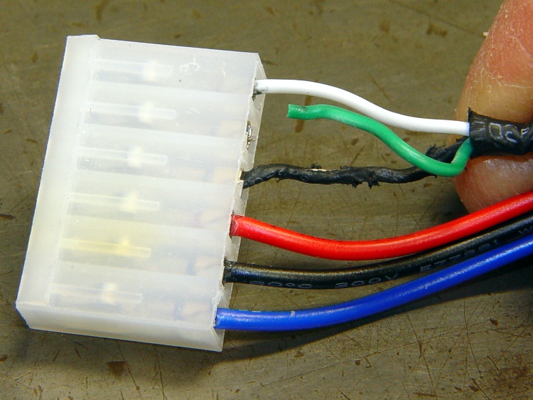
At one point along the way, the Control Panel reported the ABP temperature as 1024 °C, which seemed excessive. A bit of poking around revealed this situation on the ABP connector:
Overheated and chafed ABP connector
The connector just barely clears the top of the X axis homing switch board and the loose wires tended to rub on the top of the cable connector. I’d been meaning to fix that for a while, but now I had a real reason.
A bit of soldering and some self-vulcanizing tape later:
Strain relief on ABP connector
Also: notice the discoloration on the connector shell surrounding the Black wire? That’s the contact leading back to the MOSFET from the platform heater: a single pin carrying far more than its rated current. The shell around the contact on the Red wire (which carries the same current) isn’t discolored, which suggests the Black connector is a bit loose / poorly crimped / whatever. It looked OK to me, so I left it alone.
While I had the cable on the bench, I added a set of those right-angle pins to eliminate the risk of loose wire ends getting into the wrong places.
You can rub and you can rub, but you can’t shine shit.
Eks tells me that was one of his grandmother’s favorite sayings.
He introduced me to the concept of a “used-car polish”: high shine over deep scratches. Sometimes, that’s exactly what the job requires.
There’s also the notion of making a silk purse from a sow’s ear (attributed variously to Jonathan Swift and Anon), which someone actually did: render the ear down to a gel, extrude thread, loom cloth, and sew up a purse. Yes, it can be done, but there’s a practical limit in there somewhere.
Contrary to what you might think, this has nothing to do with a certain Thing-O-Matic. A bit of laparoscopic surgery on our front yard just revealed that our septic leach field has filled with gunk; it’s 56 years old and hadn’t been pumped for two decades before we bought the place. The next week or two should be interesting: I can do the diagnosis, but I can’t handle this repair.
The X10 RF Remote Control in the kitchen stopped working, which could mean only one thing: a set of dead AAA cells.
A negative terminal in the battery compartment showed the expected corrosion:
X10 Remote battery terminals
The corrosion evidently pushed the cell away from the terminal just enough to starve the remote.
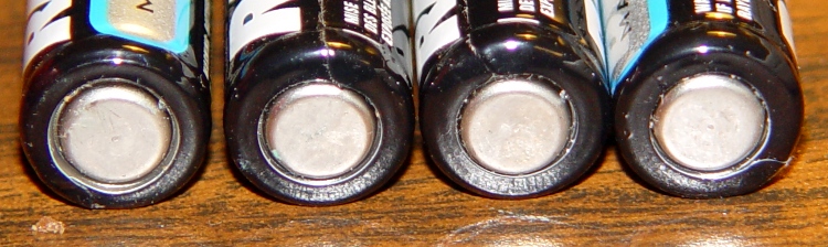
The cells, on the other paw, looked just fine:
Battery negative terminals
They’d been in there a year, sported a date code that’s still a few years in the future, and had a 1.3 V loaded output. Looks like that little bit of corrosion gave me enough of a heads-up to get the cells out before they rotted.
My Parts Heap disgorged a somewhat larger TO-5 heatsink (a Thermalloy 228B, which they no longer make) with three fins and a collar having enough spring to fit tightly around the Thermal Riser Tube. It was intended for transistors on PCBs with horizontal air flow, but I hoped it would be more effective than the smaller heatsink that comes stock with the TOM.
There’s certainly some air flow through the heatsink at the top of the arches, but I have no way of measuring that. The picture there shows another, much flatter, heatsink that I’d been using to cool the Thermal Riser after I found out how hot it was getting near the top.
This heatsink didn’t get a thermocouple mount epoxied to it and, given my experience with the first set of measurements, I didn’t bother stuffing a thermocouple between the fins.
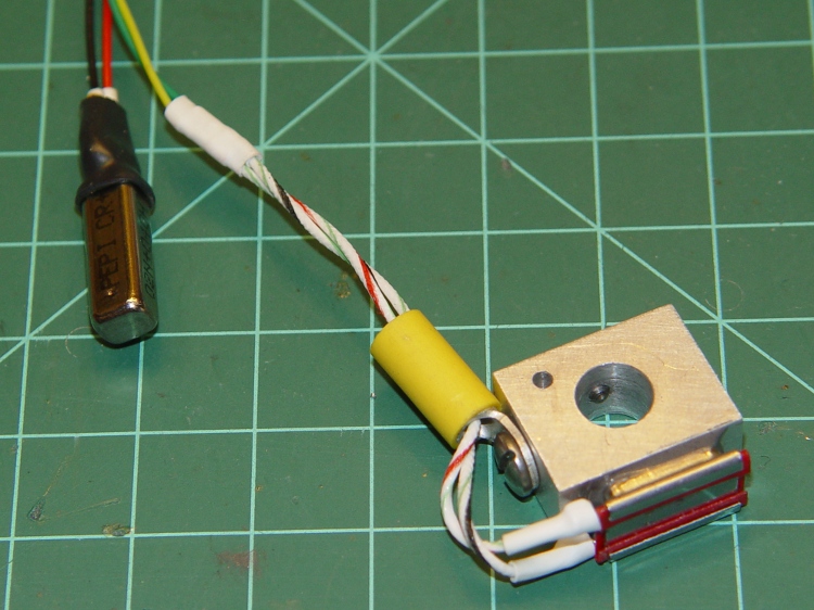
The Thermal Switch Block now has a 100 °C NC Thermal Switch epoxied to it and, barely visible to the lower right, a 40 °C NO Switch is taped to the Z stage in the corner of the acrylic support base. The switch cable looks like this:
Themal Switches – prepped and mounted
With the meter’s T1 thermocouple bead behind the 40 °C switch and T2 tucked into the Thermal Switch Block, the results look thusly:
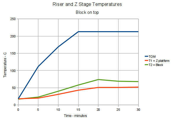
Thermal Riser and Z stage Temperature Graph – block top
The core went to 220 °C this time, with the ABP at 120 °C, and I started extruding at 20 minutes when the temperature had stabilized. The Switch Block temperature promptly dropped 6 °C as room-temperature filament entered the top of the Thermal Riser Tube at 2 rev/min × 10 cm drive dia × π = 63 mm/min ≈ 1 mm/sec.
The previous test showed that the Thermal Switch Block stabilized at 90 °C and I think this one will be about the same, despite the larger heatsink, although the while-extruding temperature hovers around 70 °C. That’s better than 90 °C, so I’ll keep monitoring it and see how it plays in warmer weather inside a cozy build chamber. Obviously, having the Extruder ram cool filament into the Thermal Core holds the temperature down.
Given those numbers, a 110 to 120 °C NC switch would be better; I’m sure one will eventually appear in my usual surplus sources. With a 30 °C margin and an assumed rise of 7 °C per 25 °C Thermal Core increase, the switch will trip when the Core passes 225 + (4 × 25) = 325 °C. That’s rather toasty, but the alternative seems to be having a switch that kicks out on a hot day.
As expected, the Z stage temperature passed 40 °C at 10 minutes and the (yellow) Low Overtemperature LED blinked on. I wasn’t too surprised at that; the previous test had a cold ABP. I’ll move that switch to the top of the acrylic arch, taped against the base of the Filament Drive frame where it can measure the effect of the Thermal Riser on the plastic base. That picture shows the potential for high temperatures at that spot.
The original data:
Thermal Riser and Z stage Temperatures – block at top
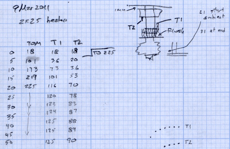
Using pretty much the same setup as before, I put the Thermal Switch Block at the top of the MK5 Thermal Riser Tube and the little heatsink at the bottom. The heatsink sat between the bolt head and left just enough room that I could snake the thermocouple bead into the brass tube, so these temperatures should be much more representative of the actual Thermal Riser.
After getting everything stuck together, I discovered that I’d interchanged the thermocouple leads. Rather than fixing that, take note that the T1 and T2 datasets represent different objects, but the same physical position: T1 on the bottom, T2 on the top.
I skipped the staged warmup, cried “Fire the Thing-O-Matic!” and ran it to 225 °C while recording temperatures every 5 minutes along the way. The graph looks like this:
Thermal Riser Tube Temperature Graph – block on top
They’re not quite exponentials, because the Core temperature gets flattened at the top, but they’re still pretty.
The top-to-bottom temperature differential has increased to 35 °C, although the top temperature still hits 90 °C. I think there are countervailing forces at work:
The thermocouple is in better contact with the Heatsink: the bottom of the tube really is hotter with the Heatsink at that end.
The Thermal Block gives a better measure of the top-of-Tube temperature, because that thermocouple is intimately connected to the Block. The Tube top is about the same temperature, but the previous Heatsink temperatures were lower.
In short, I trust these readings a bit more than the previous ones.
But, as before, the Switch Block is still too hot for a 100 °C Thermal Switch. The next step is to add a somewhat larger heatsink from my Parts Heap and see what happens.
The general idea: measure the Thermal Riser Tube temperatures, so as to figure out where to put the Thermal Cutout Switch that will kill the Thing-O-Matic if the cartridge heater drive circuitry gets stuck on. Ideally, there will be a location suitable for the 100 °C NC switch I have on hand, but you’d use the same technique to make sure any switch would work.
So, to begin.
With the Thermal Switch Block just over the bolt heads and the small heatsink just under the acrylic sheet at the top, a pair of thermocouples attached to my old Fluke 52 meter reported temperatures.
The top thermocouple (T2 data) touches, ever so gently, the small heatsink, so it’s reporting mostly heatsink temperature and bit of the surrounding air. It moved slightly after the first measurement, despite the masking tape visible in the upper right corner of the picture.
The bottom thermocouple (T1 data) is tucked into the small hole in the Switch Block, so it’s reporting the real block temperature that the Thermal Switch will eventually experience.
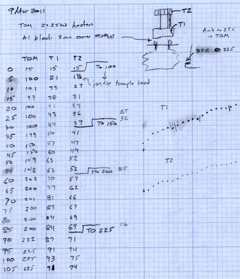
A third thermocouple is taped in the corner of the Z axis stage against the acrylic arch, directly beside a cartridge heater inside the insulation wrap. During these proceedings that temperature rose from 25 °C ambient (due, most likely, to hand warmth while positioning all this stuff) to about 35 °C.
And, of course, the standard thermocouple on the MK5 Core reports the actual temperature inside the insulation wrap.
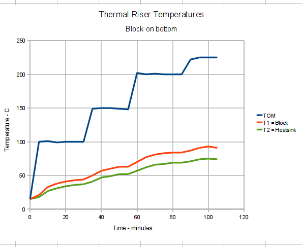
I raised the MK5 temperature in 50 °C steps, then 25 °C to 225 °C, waiting until the Block temperature more-or-less stabilized, while recording temperatures every 5 minutes. On this time scale, the Thermal Core temperature stabilized over the course of a single measurement.
With at that in mind, the results look like this:
Thermal Riser Tube Temperature Graph – block on bottom
At normal extruding temperatures above 200 °C, the red trace shows the Switch Block running about 15°C above green Heatsink trace and topping out at 91 °C. The top of the Riser Tube is somewhat cooler with that big Block hanging on the bottom, too: 70 to 74 °C, rather than the 83 °C I measured there.
The Block temperature increases by 7 °C when the Core increases by 25 °C, obviously depending on a bunch of nonlinear effects. A rash extrapolation suggests a 100 °C switch would trip before the Core hit 275 °C.
However, that Block gets uncomfortably close to 100 °C, which is the point where the Thermal Switch will go click and kill the whole show. I’d rather have a bit more headroom to allow for warm summer weather and a heated build chamber.
So the next experiment puts the Thermal Switch Block at the top of the Thermal Riser Tube…
The best place to mount a thermal switch (or a thermal sensor, depending on how much you trust your circuitry) is on the MK5 Thermal Core, but that’s far too hot for the switches I have in hand. As a compromise, I decided to mount the switch on the Thermal Riser tube leading vertically upward to the Filament Drive gear: good thermal contact, a solid mount, and out of harm’s way.
All the alternative locations seem worse. Tucking it inside the insulation wrap doesn’t provide a solid mechanical mount, so you don’t get a repeatable position and the leads get bent every time you move something. Bolting it to the plate over the Core looks solid, but that’s just a flat sheet of metal with four screws connecting it to the Core: no real thermal contact surrounded by lots of cooling air.
One good omen: with an operating temperature well under 100 °C, JB Industro Weld epoxy will work fine and eliminate any need for fussy clamps and fittings.
So I sawed off a random chunk of aluminum plate, squared it up in the Sherline mill, and poked a few holes in it. This doodle has dimensions roughly equivalent to the final object, but absolutely nothing is critical other than the 5/16 inch central hole:
Switch block sketch
The 4-40 setscrew secures the block to the Thermal Riser. Aluminum expands considerably more than stainless steel, so I dropped a snippet of PTFE wire insulation into the hole as a rubberdraulic plunger.
The lug on the top provides strain relief for the wires; it’s not an electrical connection. The modular phone cable trailing off to the Thermal Cutout box has wires insulated with low-temperature plastic, so a few inches of Teflon hookup wire keep them out of the Danger Zone.
The small hole is just big enough for a thermocouple bead.
This is what the thing eventually looked like, but I made some measurements before sticking that switch in place: