The Smell of Molten Projects in the Morning

Ed Nisley's Blog: Shop notes, electronics, firmware, machinery, 3D printing, laser cuttery, and curiosities. Contents: 100% human thinking, 0% AI slop.

Category: Electronics Workbench

Electrical & Electronic gadgets

  • Under-cabinet Lamp Brackets

    These blocky brackets hold a pair of LED light strips in the recess under our 1955-era kitchen cabinets, to let the light cover the entire counter:

    Kitchen Light Bracket
    Kitchen Light Bracket

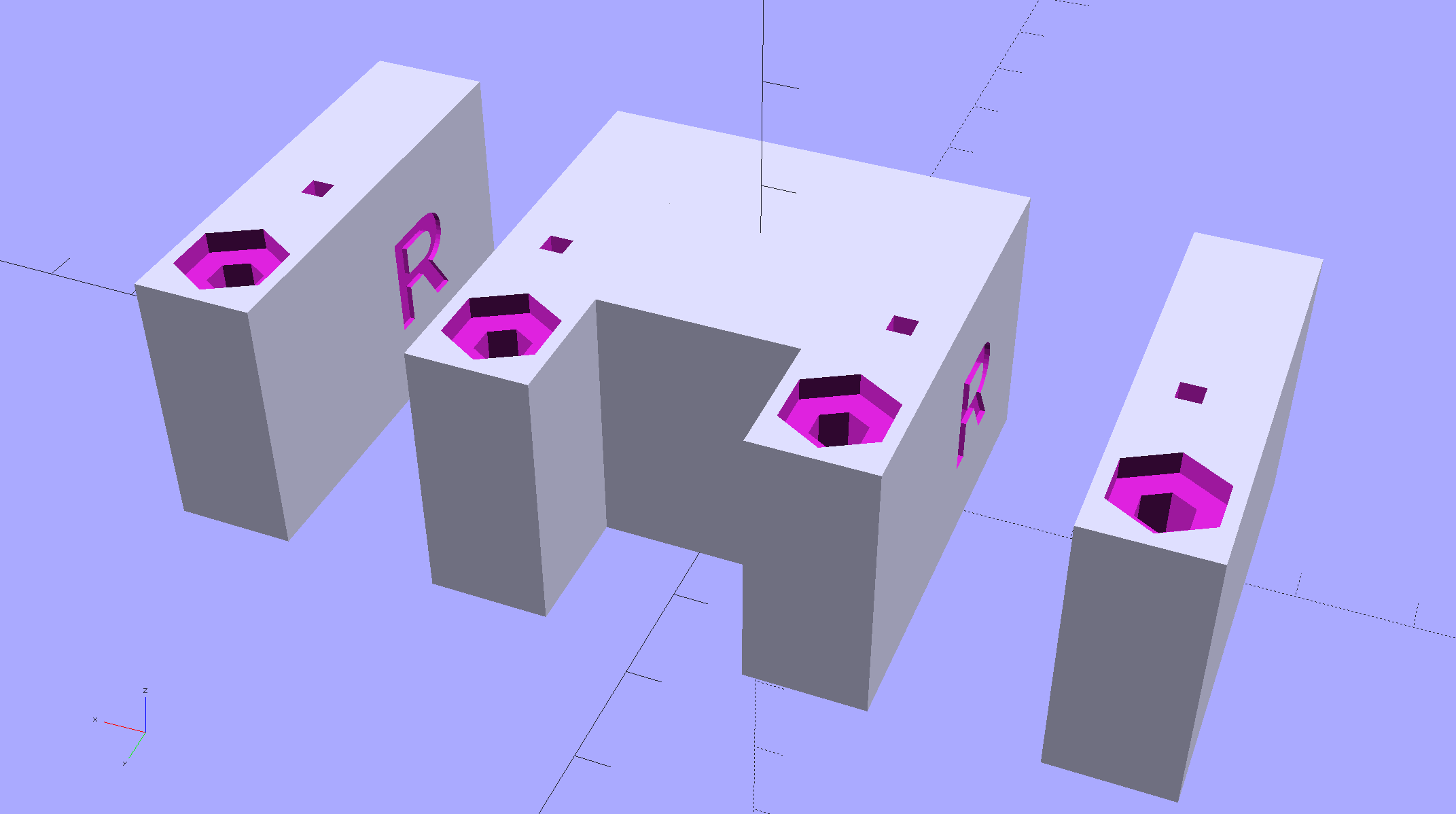
    The large holes are for drywall screws into the cabinet, the smaller ones for 2.5 mm SHCS holding the strips to the brackets. I drilled those little holes out and installed 4-40 brass inserts; this being a one-off installation, the source code doesn’t include that change.

    There’s not much to see after they’re installed:

    Under-cabinet light bracket - center joiner
    Under-cabinet light bracket – center joiner

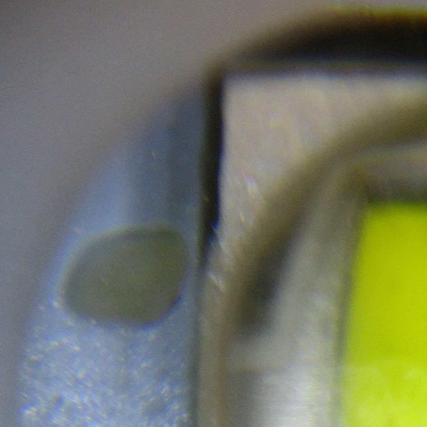
    I’d hoped to swap the ends of the strip to power it from the right end, but the guts aren’t symmetric and you can’t just flip it end-for-end:

    eShine LED Under-cabinet light - disassembled
    eShine LED Under-cabinet light – disassembled

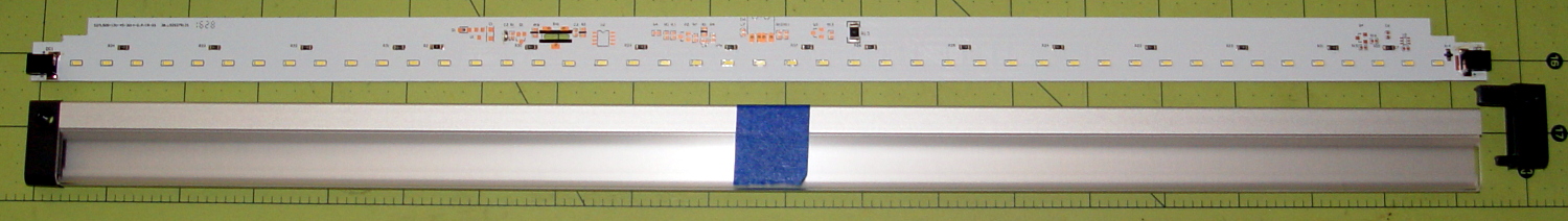
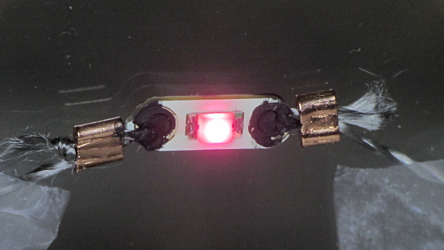
    That’s an add-on unit without the IR proximity sensor circuitry and power switch, but with the same overall layout. You take it apart by pressing the obvious latch on one of the endcaps, then gently prying the plastic away from the aluminum extrusion, taking care not to wreck the coaxial socket. Reassemble in reverse order.

    The OpenSCAD source code as a GitHub Gist:


    // Mounting brackets for eShine under-counter LED lights
    // Ed Nisley KE4ZNU December 2016
    //- Extrusion parameters must match reality!
    ThreadThick = 0.25;
    ThreadWidth = 0.40;
    HoleWindage = 0.2;
    Protrusion = 0.1; // make holes end cleanly
    inch = 25.4;
    function IntegerMultiple(Size,Unit) = Unit * ceil(Size / Unit);
    //———-
    // Dimensions
    MountHeight = (1 + 3/16) * inch – 5.0; // under-cab space – base thickness
    THREADOD = 0;
    HEADOD = 1;
    LENGTH = 2;
    WoodScrew = [4.0,8.3,41]; // 8×1-5/8 Deck screw
    WoodScrewRecess = 2.0;
    LEDScrew = [2.0,4.5,8.0]; // M2.5×10 SHCS
    LEDScrewOffset = [1.0,8.2,0]; // hole offset from center point
    JoinerLength = 18.1; // joiner between strips
    EndBlock = [11.0,28.5,MountHeight]; // mounting block size for ends
    //———————-
    // Useful routines
    module PolyCyl(Dia,Height,ForceSides=0) { // based on nophead's polyholes
    Sides = (ForceSides != 0) ? ForceSides : (ceil(Dia) + 2);
    FixDia = Dia / cos(180/Sides);
    cylinder(d=(FixDia + HoleWindage),h=Height,$fn=Sides);
    }
    // End mounting block with proper hole offsets
    module EndMount(Side = "L") {
    LSO = [((Side == "L") ? 1 : -1)*LEDScrewOffset[0],LEDScrewOffset[1],LEDScrewOffset[2]];
    difference() {
    union() {
    cube(EndBlock,center=true);
    translate([0,1.5*WoodScrew[1],0])
    cube(EndBlock,center=true);
    }
    translate(LSO + [0,0,-EndBlock[2]])
    rotate(180/4)
    PolyCyl(LEDScrew[THREADOD],2*EndBlock[2],4);
    translate([0,(EndBlock[1] + 1.5*WoodScrew[1])/2,-EndBlock[2]])
    rotate(180/6)
    PolyCyl(WoodScrew[THREADOD],2*EndBlock[2],6);
    translate([0,(EndBlock[1] + 1.5*WoodScrew[1])/2,(EndBlock[2]/2 – WoodScrewRecess)])
    rotate(180/6)
    PolyCyl(WoodScrew[HEADOD],WoodScrewRecess + Protrusion,6);
    translate([((Side == "L") ? 1 : -1)*EndBlock[0]/2,0,0])
    rotate([90,0,((Side == "L") ? 1 : -1)*90])
    translate([0,0,-2*ThreadThick])
    linear_extrude(height=4*ThreadThick,convexity=3)
    text(Side,font=":style=bold",valign="center",halign="center");
    }
    }
    module MidMount() {
    XOffset = (JoinerLength + EndBlock[0])/2;
    union() {
    translate([XOffset,0,0])
    EndMount("L");
    cube([JoinerLength,EndBlock[1],EndBlock[2]] + [2*Protrusion,0,0],center=true);
    translate([-XOffset,0,0])
    EndMount("R");
    }
    }
    //———-
    // Build them
    translate([0,0,EndBlock[2]/2]) {
    translate([-(JoinerLength + 2*EndBlock[0]),0,0])
    EndMount("L");
    MidMount();
    translate([(JoinerLength + 2*EndBlock[0]),0,0])
    EndMount("R");
    }

  • Sony HDR-AS30V vs. Lithium Ion 18650 Cells

    These items came near enough to produce an irresistible force:

    Sony HDR-AS30V vs 18650 cells - side view
    Sony HDR-AS30V vs 18650 cells – side view

    How can you look at that layout and not jump to the obvious conclusion?

    The front view suggests enough room for a stylin’ case:

    Sony HDR-AS30V vs 18650 cells - end view
    Sony HDR-AS30V vs 18650 cells – end view

    You’d need only one cell for the camera; I happened to have two in my hand when the attractive force hit.

    The camera is 24.5 ⌀ x 47 tall x 71.5 overall length (67.8 front-to-door-seating-plane).

    The ATK 18650 cells are 19 ⌀ x 69 long, with the overlong length due to the protection PCB stuck on the + end of the cylinder. You can get shorter unprotected cells for a bit less, which makes sense if you’re, say, Telsa Motors and building them into massive batteries; we mere mortals need all the help we can get to prevent what’s euphemistically called “venting with flame“.

    Although I like the idea of sliding the cell into a tubular housing with a removable end cap, it might make more sense to park the cell over the camera in a trough with leaf-spring contacts on each end and a lid that snaps over the top. That avoids threaded fittings, figuring out how to get an amp or so out of the removable end cap contact, and similar imponderables.

    think it’s possible to drill a hole through the bottom of the camera at the rear of the battery compartment to pass a cable from a fake internal cell to the external cell. Some delicate probing will be in order.

    In round numbers, those 18650 cells allegedly have three times the actual capacity of the camera’s flat battery and cost about as much as the not-so-cheap knockoff camera cells I’ve been using.

  • J5 V2 Flashlight: Current Draw

    Just for fun, I measured the J5 V2 flashlight’s current, by the simple expedient of unscrewing the cap and bridging the battery-to-case-threads gap with a multimeter:

    J5 V2 Flashlight - negative cell terminal
    J5 V2 Flashlight – negative cell terminal

    The results:

    • High: 3 A
    • Medium: 1.5 A
    • Low: 0.7 A

    As nearly as I can tell, they’re connecting the 18650 cell directly across the LED for High and PWM-ing it down to 50% and 25%. The PWM frequency is low enough to be visible during eye saccades and flashlight motions.

    The flashlight knows how to do all five modes without its tail cap, so the controller + FET must live behind the LED. I can’t tell if the switch in the tail cap is just a dumb pushbutton (with, it seems, a surprising & ill-controlled resistance) or doing something clever with resistive levels (because the resistance varies with each push); at some point this thing will fail in an amusing manner and I’ll take it apart to find out.

    The High setting dissipates 11 W (!) that pushes the flashlight well beyond uncomfortably warm within five minutes, so that’s not a useful long-term setting. The little alien egg beside the LED melted into a puddle during those five minutes; at least it won’t be moving anywhere else.

    Setting it to Low = 25% PWM duty cycle = 0.7 A (average, sorta-kinda), a freshly charged 18650 cell lasts for about five hours down to 3.6 V, which is pretty close to the cell’s 3.4 A·h rating (kinda-sorta, ignoring the decreasing cell voltage, etc). That suggests Medium would last maybe two hours, tops, and there’s not enough heatsinking to discover how long High would last.

    After 8.5 hours the cell was down to 3.2 V and the LED was, as you’d expect, rather dim. You could click to High for more light, of course, trading off runtime for brightness.

    The square LED emitter array produces a square light pattern that’s not aligned with the flats on the body, so if you happened to be thinking of clamping a holder onto those flats, be prepared for some custom rotation to align the pattern with the outside world. That obviously doesn’t matter in a hand-held flashlight, but a bike headlight might look weird.

    The zoom slider goes from a focused square (at full extension) to a well-filled round disk (at minimum length) with a diameter about five times the square’s side. I think the smooth zoom motion comes from grease-on-O-ring viscosity rather than precision machining.

    The original back of the envelope data:

    J5 V2 Flashlight - current and runtime
    J5 V2 Flashlight – current and runtime
  • Mica Compression Capacitor: Unsolderable Pins

    The mica compression capacitors have a finish on the pins that turned out to be completely un-solderable:

    Mica compression capacitor - solder vs pin
    Mica compression capacitor – solder vs pin

    Some casual searching suggests this is a problem with sulfur contamination of the tin-lead solder layer. I can’t vouch for any of that, as the flat areas forming the capacitor seem to be silver-plated, but …

    After some flailing around, I completely disassembled the capacitor, applied 800 grit sandpaper to remove all of the solder / flux / corrosion / tarnish / surface plating from the pins, dabbed on some RMA flux, then applied a thin layer of solder to both sides. Fortunately, the capacitor could be disassembled; they don’t make ’em like that any more.

    The solder layers must be thin, because the slots in the ceramic base must pass two or three pins apiece: four or six solder layers add too much thickness. Solder-wick is my friend!

    For reference, the 700 pF side looks like this:

    Mica compression capacitor - 700 pF disassembled
    Mica compression capacitor – 700 pF disassembled

    The steel washer does not have a mica washer underneath (as does the washer on the 400 pF right side). The two grayish steel plates go on the top.

  • J5-V2 700 lm Flashlight: QC FAIL, Redux

    The inside of the replacement J5 V2 Tactical Flashlight doesn’t have quite as much dirt on the LED emitter, but it’s still pretty bad:

    J5-V2 Flashlight - LED crud - second unit
    J5-V2 Flashlight – LED crud – second unit

    The small white dingus at about 10 o’clock seems to be a plastic shred stuck on end to the emitter lens. Here’s a better look, rotated a quarter-turn counterclockwise:

    J5-V2 Flashlight - LED crud detail - second unit
    J5-V2 Flashlight – LED crud detail – second unit

    There’s also an alien egg glued to the heatsink beside the LED:

    J5-V2 Flashlight - random pellet - second unit
    J5-V2 Flashlight – random pellet – second unit

    I’m hoping it’s another random plastic blob.

    There’s no point in returning this one; it’ll suffice for my purposes. However, given two random samples, I’d say the J5 Tactical Flashlight factory, wherever it may be in China, is really filthy.

    I’d hoped that paying a bit more for a “tactical” flashlight, instead of going bottom dollar, would yield a better product. Maybe it did?

  • J5-V2 700 lm Flashlight: QC FAIL

    So I picked up a J5-V2 Tactical Flashlight as a possible bike headlight, on the basis of a 750 (“max output”) lumen LED, zoomable beam, and use of standard 18650 lithium cells (rather than USB charging). The geometry required to stick it on the Tour Easy remains a puzzle, but an az-el dingus replacing an upper fairing mount may work well enough.

    Anyhow, it seems the LED in this flashlight fell on the floor during assembly, where the (silicone?) LED emitter lens picked up a remarkable amount of dirt:

    J5-V2 Flashlight - LED crud
    J5-V2 Flashlight – LED crud

    The inside of the front focusing lens carries an array of scratches or, perhaps, a greasy fingerprint that serves the same purpose:

    J5-V2 Flashlight - internal lens scratches
    J5-V2 Flashlight – internal lens scratches

    All vendors tell you to contact them before posting a critical review, although they often don’t provide much in the way of contact information. I sent a note with photos to J5 through their website’s contact info; having not heard anything after three days, I’ll fire up the Amazon return process …

  • Wearable Electronics: Connections

    Although I’m not the type of guy who thinks twinkly LEDs will enhance his apparel, one of Mary’s quilting thread sources had a closeout deal on their “wearable electronics”, including a large cone of stainless steel thread / yarn:

    Stainless steel thread
    Stainless steel thread

    … CR2032 lithium cells & holders, plus assorted LEDs on small PCBs.

    The usual advice for connecting the thread seems to involve knotting it through the PCB holes, then sewing it to the backing fabric. Alas, I’m bad with knots and the stainless steel yarn isn’t all that cohesive:

    Emerald LED - Stainless steel thread - knotted
    Emerald LED – Stainless steel thread – knotted

    The holder has an even smaller hole, but Mary gave me a needle threader that helped:

    CR2032 - Stainless steel thread - knotted
    CR2032 – Stainless steel thread – knotted

    Some advice found on The InterTubes suggests using copper crimp beads (perhaps with solder) to prevent the thread from completely unraveling and keep the thread loop tight around the PCB hole:

    Rose LED - Stainless steel thread - Crimp bead - Wire Glue
    Rose LED – Stainless steel thread – Crimp bead – Wire Glue

    Beadworkers use crimping pliers that leave a tidy dent; I mashed the beads with a needlenose pliers and called it good.

    The LEDs seem to be white LEDs with filters or, perhaps, blue / violet LEDs with different phosphors: their forward voltages look more blue than red or green. Everybody in this field depends on the minor miracle that lithium cell voltages match blue LED forward drops closely enough that you can get away without a ballast resistor.; the cell’s 20-ish Ω internal resistance doesn’t hurt in the least. An interesting white paper (SWRA349) from TI explores the effect of current on cell capacity and how to size a parallel capacitor that reduces the peak battery current.

    The black gunk is Wire Glue, which costs about five bucks for a lifetime supply in a small jar (or nigh onto 15 bucks via Amazon Prime) and is basically carbon powder in a water-based binder. Apply a dab to the connection and the water evaporates to leave the carbon + binder behind.

    That works better on joints that don’t move, which is precisely what you don’t have in a wearable electronic situation. You can see the crumbling Wire Glue after the trip back from a Squidwrench meeting:

    CR2032 - Stainless steel thread - Crimp bead - Wire Glue
    CR2032 – Stainless steel thread – Crimp bead – Wire Glue

    I also picked up a Permatext Rear Window Defogger repair kit (09117, if you’re looking) that seems to be a staggeringly expensive way to get a tenacious high-current conductive adhesive. More on that later.

    The yarn runs 3.5 Ω/ft, much lower than Adafruit’s three-ply yarn (10 Ω /ft), and suggests itself for flexible connections, EMI gaskets, and suchlike.

    Those LEDs are taped to the kitchen window, where they cast a cool light over the table, with the battery holders sitting on the sash. I’d just replaced some data logger CR2032 cells, so they’re running from nearly dead lithium batteries.

    For future reference: 2.77 V and falling, pushing less than 2 mA through the LEDs.