Ed Nisley's Blog: Shop notes, electronics, firmware, machinery, 3D printing, laser cuttery, and curiosities. Contents: 100% human thinking, 0% AI slop.
The first two charges for those Baofeng BL-5 batteries show that the actual capacity isn’t quite up to the 1800 mA·h spec:
Baofeng BL-5 Packs – First two charges
The (meager) instructions say that the batteries will reach “full capacity” after three charges. Unless there’s a miracle waiting in the wings for that third charge, I very much doubt that they’ll get any better than the 1400 to 1500 mA·h you see in that graph. Note that the two batteries have quite different capacities and that the capacity for Pack B decreased on the second charge (purple vs. green trace).
Compare that with the Wouxun batteries (plotted with Gnuplot, rather than a screen grab):
Wouxun 7.4 V Packs
Those are all at 250 mA, which is certainly less than the peak current and probably more than the average current. It’s close enough for now, anyway, and shows that the Wouxun batteries actually live up to their spec.
Huh. Who’d’a thunk it?
It looks like the blinky lights should go into power-save mode under 7 V, because there just isn’t that much capacity left when the cells start rolling over the edge of the cliff.
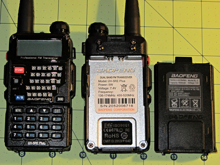
After I mentioned I was thinking of repurposing the nearly unused lithium-ion batteries from the Wouxun KG-UV3D radios for a blinky light, Dragorn of Kismet introduced me to his Baofeng UV-5 radio. The radio itself seems to be the worst amateur radio you’d be willing to use, but when seen as a standardized battery and drop-in charger with a free radio and antenna tossed into the deal, it’s not all that bad:
Baofeng UV-5RE radio – overview
The Wouxun and Baofeng 7.4 V batteries allegedly have similar capacities: 1700 vs 1800 mA·h. The Baofeng also has a 3800 (or 3600) mA·h pack that extends well below the base of the radio (not all large packs seem to be compatible with the UV-5RE radios I got); that would be roughly equivalent to the larger packs that power the Wouxun / APRS / voice gadgetry on the bike.
The Baofeng battery pack is smaller and has features that seem less likely to misbehave on a bike.
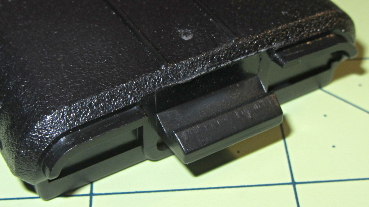
It has a latching tab with a ramp and a positive notch, with ridges around the edge that engage the radio shell:
Baofeng UV-5RE radio – battery latch tab
The radio body (which is what I must duplicate) has a movable latch tab above the battery contact pins, so the latch holds the battery into the compartment. The spring-loaded pin pairs are wired in parallel, presumably for redundant contact with each battery terminal:
Baofeng UV-5RE radio – battery compartment latch and contacts
The battery terminal pads are reasonably well protected by the tab:
Baofeng UV-5RE radio – battery contact pads
The battery slides into the radio compartment and latches with a snap. Two holes on the battery base engage a pair of pegs on the radio case:
Baofeng UV-5RE radio – battery base detail
The holes are rounded rectangles and the pegs have one corner sliced off. The pegs seem entirely too fragile and not well suited for 3D printing, so some metalwork may be in order. The pegs must resist only pulling forces perpendicular to the case back, not sliding forces, and the case constrains side-to-side motion.
The two square posts (with two others not shown) form the “feet” that support the radio when it’s standing on the desk or in the charger.
Now, to doodle up the dimensions and measure the actual capacity.
Speaking of capacity, BL-5 batteries on eBay range from $23 for “genuine Baofeng” that may or may not actually have that name on the label, all the way down to $8 for the usual no-name equivalent.
The first Wouxun (evidently pronounced “ocean”) KG-UV3D HT spent a month or two in my bike, lashed to a kludged version of the APRS+voice interface box and powered by its own lithium-ion pack. After I got the circuit worked out and built a duplicate, I picked up a second HT for Mary’s bike; as a result, that battery pack never got much use.
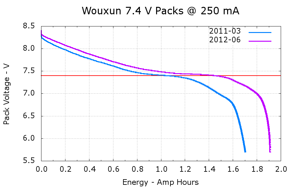
A pair of discharge tests shows the difference:
Wouxun 7.4 V Packs
The 2011-03 battery has almost exactly the rated 1.7 A·h capacity, at least if you’re willing to run it down to 6 V, and the 2012-06 pack delivers 1.9 A·h. Electronic gadgets measure state-of-charge using the battery voltage, so the older pack “looks” like it has much less capacity: it runs about 100 mV lower than the newer pack out to 1.2 A·h, then falls off the cliff. Looks to me like one of the two cells inside is fading faster than the other; so it goes.
I’m still thinking of using these to power some LED taillights, because they have a nice form factor and built-in latches:
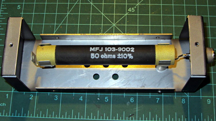
If you happen to own an MFJ-260B dummy load and it’s giving you weird SWR values, take the cover off and roll the power resistor in its mounting clips:
MFJ-260B HF Dummy Load – power resistor
My buddy Aitch discovered that oxide / corrosion / dirt buildup between the resistor and the clips can produce absolutely baffling results, even while passing enough current to warm up the element, far more power than you’d think would burn away any crud.
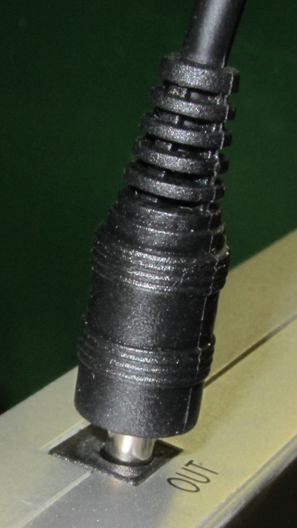
Rather than cutting the pack apart, I buttered up the end of an intact plug with some ABS solvent glue (a hellish homebrew mixture of acetone and MEK), rammed it into the socket, and held it in place for a minute:
LiIon Pack – undamaged plug insertion
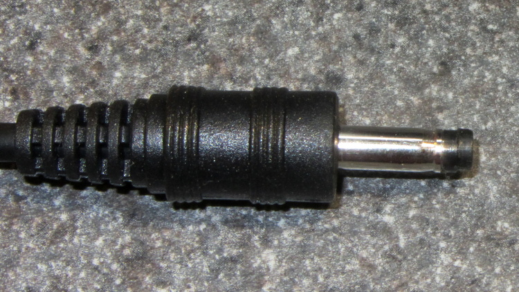
The tip emerged on the first try:
LiIon Pack – rescued plug tip joined
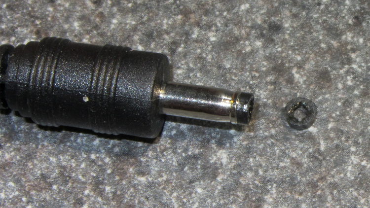
Even better, it cracked off the plug without too much effort:
LiIon Pack – rescued plug tip separated
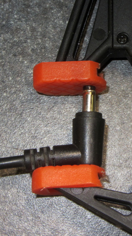
More solvent glue and a few hours of clamping worked fine:
I want to stress-test some LEDs for the long-stalled bike taillight project with a high current / low duty cycle drive. The usual specs give something like 100 mA at 10% duty cycle in a 100 μs period, but maybe they’ll withstand more abuse than that; I don’t have any specs whatsoever for these LEDs. The usual DC rating is 20 mA, so 100 mA at 20%, say 2 ms in a 10 ms period, should give the same average power as the DC spec. I plan to run them continuously until some failures to pop up or it’s obvious they’re doing just fine.
Although this would be a dandy Arduino project, a classic 555 timer IC makes more sense for something that must run continuously without changing anything. The usual 555 circuit restricts the duty cycle to more than 50% for high-active pulses, a bit over the 20% this task calls for. The simplest workaround is a Schottky diode across the discharge resistor to separate the two current paths: charge uses the upper resistor, discharge the lower, with the diode forward drop thrown in to complicate the calculations.
Rather than putz around with calculation, a few minutes iterating with Linear Technologies’ LTSpice IV produces a reasonable result:
NE555 pulse generator
In round numbers, a 1 μF timing capacitor, 2.7 kΩ charge resistor, and 13 kΩ discharge resistor do the trick. Given the usual capacitor tolerances, each resistor should include a twiddlepot of about half the nominal value: 1 kΩ and 5 kΩ, respectively.
I’m thinking of repurposing those Wouxun KG-UV3D batteries for this task and found a 7.5 V 3.5 A wall wart in the heap that will be close enough for the test rig. The 555 output should drive a logic-level MOSFET just fine, although even an ordinary FET would probably be OK for the relatively low current required for LED toasting.
Having been unable to find a single listing of all the ARRL Hands-On Radio columns(*) by Ward Silver, N0AX, in QST magazine, I scraped their lists, did some cleanup, and roughly categorized each column’s topic. If you want to bootstrap yourself (or someone you know) from zero to pretty good, he can get you there!
[Update: (*) You must be an ARRL member to access the collection, but you need not hold an amateur radio license…]
Exp
Title
DC
Audio
Digital
Power
RF
Theory
1
The Common-Emitter Amplifier
x
x
x
x
2
The Emitter-Follower Amplifier
x
x
x
x
3
Basic Operational Amplifiers
x
x
x
4
Active Filters
x
x
5
The Integrated Timer
x
6
Rectifiers and Zener References
x
x
7
Voltage Multipliers
x
x
8
The Linear Regulator
x
x
9
Designing Drivers
x
x
x
x
10
Using SCRs
x
x
11
Comparators
x
x
x
x
12
Field Effect Transistors
x
x
x
x
x
x
13
Attenuators
x
x
x
14
Optocouplers
x
x
x
15
Switchmode Regulators, Part 1
x
x
16
Switchmode Regulators, Part 2
x
x
17
The Phase-Shift Oscillator
x
x
x
18
Frequency Response
x
x
x
19
Current Sources
x
x
x
20
The Differential Amplifier
x
x
21
The L-Network
x
x
22
Stubs
x
x
23
Open House in the N0AX Lab
24
Heat Management
x
x
25
Totem Pole Outputs
x
x
x
x
26
Solid-State RF Switches
x
27
Scope Tricks
x
x
x
x
x
x
28
The Common Base Amplifier
x
x
x
x
29
Kirchhoff’s Laws
x
x
x
30
The Charge Pump
x
x
x
x
31
The Multivibrator
x
x
x
32
Thevenin Equivalents
x
33
The Transformer
x
x
x
x
34
Technical References
x
35
Power Supply Analysis
x
x
x
36
The Up-Down Counter
x
37
Decoding for Display
x
38
Battery Charger
x
x
39
Battery Charger, Part 2
x
x
40
VOX
x
41
Damping Factor
x
x
x
42
Notch Filters
x
x
x
43
RF Oscillators, Part 1
x
x
44
RF Oscillators, Part 2
x
x
45
RF Amplifiers, Part 1
x
x
x
46
Two Cs: Crystal and Class
x
x
47
Toroids
x
x
48
Baluns
x
x
49
Reading and Drawing Schematics
x
50
Filter Design 1
x
x
x
51
Filter Design 2
x
x
x
52
SWR Meters
x
53
RF Peak Detector
x
x
x
54
Precision Rectifiers
x
x
55
Current/Voltage Converters
x
x
x
x
56
Design Sensitivities
x
57
Double Stubs
x
58
Double Stubs II
x
59
Smith Chart Fun I
x
x
60
Smith Chart Fun 2
x
x
61
Smith Chart Fun 3
x
x
62
About Resistors
x
x
x
x
63
About Capacitors
x
x
x
x
64
Waveforms and Harmonics
x
x
x
x
x
65
Spectrum Modification
x
x
x
66
Mixer Basics
x
x
x
x
67
The Return of the Kit
68
Phase Locked Loops, the Basics
x
x
x
x
69
Phase Locked Loops, Applications
x
x
x
70
Three-Terminal Regulators
x
x
x
71
Circuit Layout
x
x
x
x
x
x
72
Return Loss and S-Parameters
x
x
73
Choosing an Op Amp
x
x
x
74
Resonant Circuits
x
x
x
75
Series to Parallel Conversion
x
x
76
Diode Junctions
x
x
x
77
Load Lines
x
x
x
x
78
Bridge Circuits
x
x
x
79
Pi and T Networks
x
x
x
80
Battery Capacity
x
x
x
81
Synchronous Transformers
x
x
82
Antenna Height
x
x
83
Circuit Simulation, Part One
x
x
x
x
x
x
83
Circuit Simulation, Build and Test
x
x
x
x
x
x
85
Circuit Simulation, Complex Parts
x
x
x
x
x
x
86
Viewing Waveforms in LTspice
x
x
x
x
x
87
Elsie Filter Design, Part 1
x
x
88
Elsie Filter Design, Part 2
x
x
89
Overvoltage Protection
x
x
x
x
90
Construction Techniques
x
x
x
x
91
Common Mode Choke
x
x
x
92
The 468 Factor
x
x
93
An LED AM Modulator
x
94
SWR and Transmission Line Loss
x
x
95
Watt’s In a Waveform?
x
x
x
x
x
96
Open Wire Transmission Lines
x
97
Programmable Frequency Reference
x
x
x
98
Linear Supply Design
x
x
x
99
Cascode Amplifier
x
x
x
x
100
Hands-On Hundred
101
Rotary Encoders
x
102
Detecting RF, Part 1
x
x
x
x
103
Detecting RF, Part 2
x
x
x
x
104
Words to Watch For
x
105
Gain-Bandwidth Product
x
x
x
x
106
Effects of Gain-Bandwidth Product
x
x
x
107
PCB Layout, Part 1
x
x
x
x
x
x
108
PCB Layout, Part 2
x
x
x
x
x
x
109
PCB Layout, Part 3
x
x
x
x
x
x
110
PCB Layout, Part 4
x
x
x
x
x
x
111
Coiled-Coax Chokes
x
112
RFI Hunt
x
x
113
Radiation Patterns
x
x
114
Recording Signals
x
x
115
All About Tapers
x
x
116
The Quarter-Three-Quarter Wave Balun
x
117
Laying Down the Laws
x
118
The Laws at Work
x
119
The Q3Q Balun Redux
x
120
Power Polarity Protection
x
x
Corrections, amendations, commentary? Let me know…