Ed Nisley's Blog: Shop notes, electronics, firmware, machinery, 3D printing, laser cuttery, and curiosities. Contents: 100% human thinking, 0% AI slop.
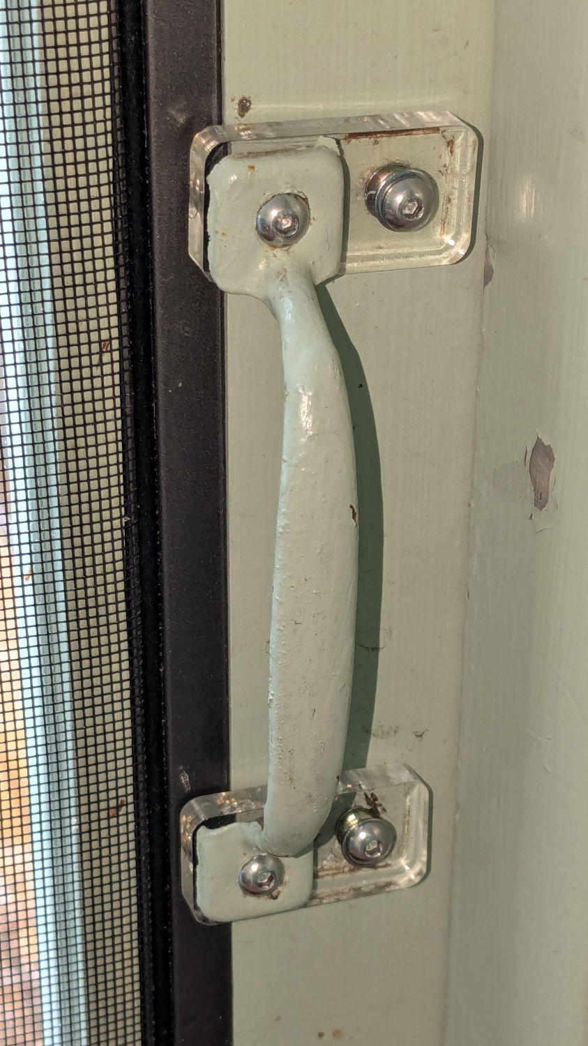
For unknown reasons, the handle on the porch screen door was installed less than one finger width from the frame, so I conjured a pair of plastic plates shifting it far enough to prevent finger pinches and avoid the screws for the outside handle:
Porch door handle repositioning
The original holes now have M4 threaded wood inserts and the holes in the ¼ inch acrylic have M4 heat-staked brass inserts, mostly because I had everything on hand.
This was part of a project to trim the bottom of the door to clear the porch floor boards, which evidently continued warping after they trimmed the door to fit:
Porch door trimming
That thin blue line suggests the highest part of the floor was once near the bottom of the picture, but it’s now the lowest part. The highest part is now near the hinge side near the top of the picture, firmly jamming the door in place.
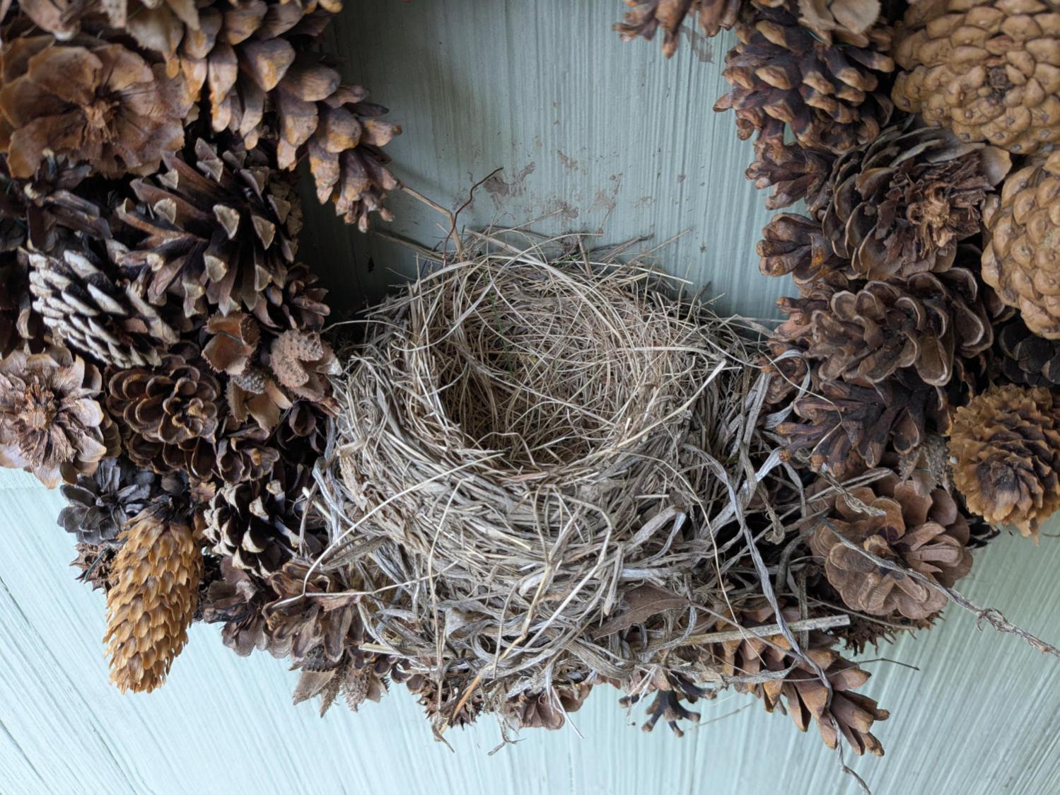
They’re considerably larger and we hoped would be more able to repel attackers. They also seemed to get off to a late start, as we saw young robins hopping around the yard with other adults while these birds were building their nest, so this may have been their second nest of the season.
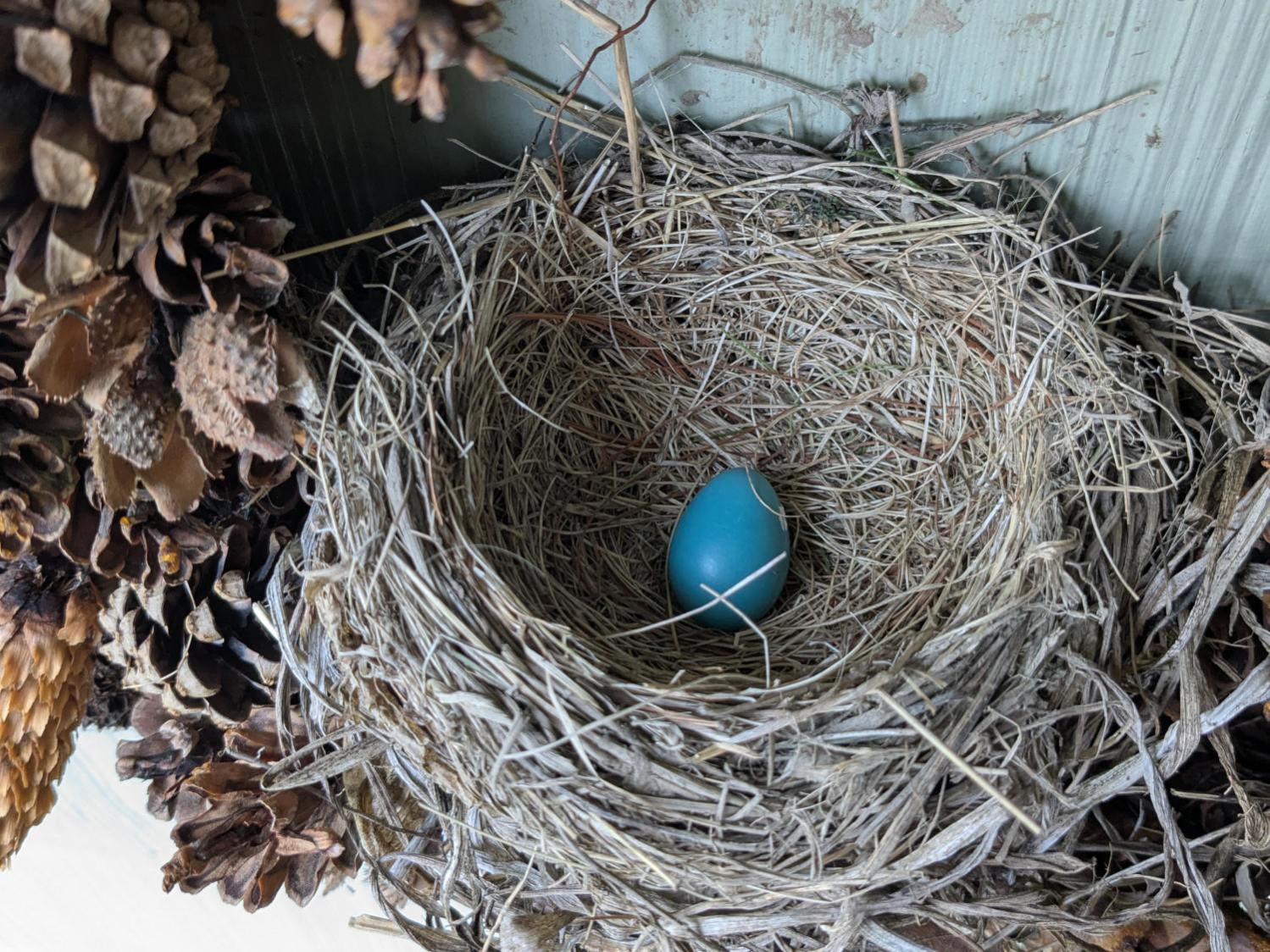
The first egg appeared on 5 May:
Wreath Robin Nest – 2025-05-18
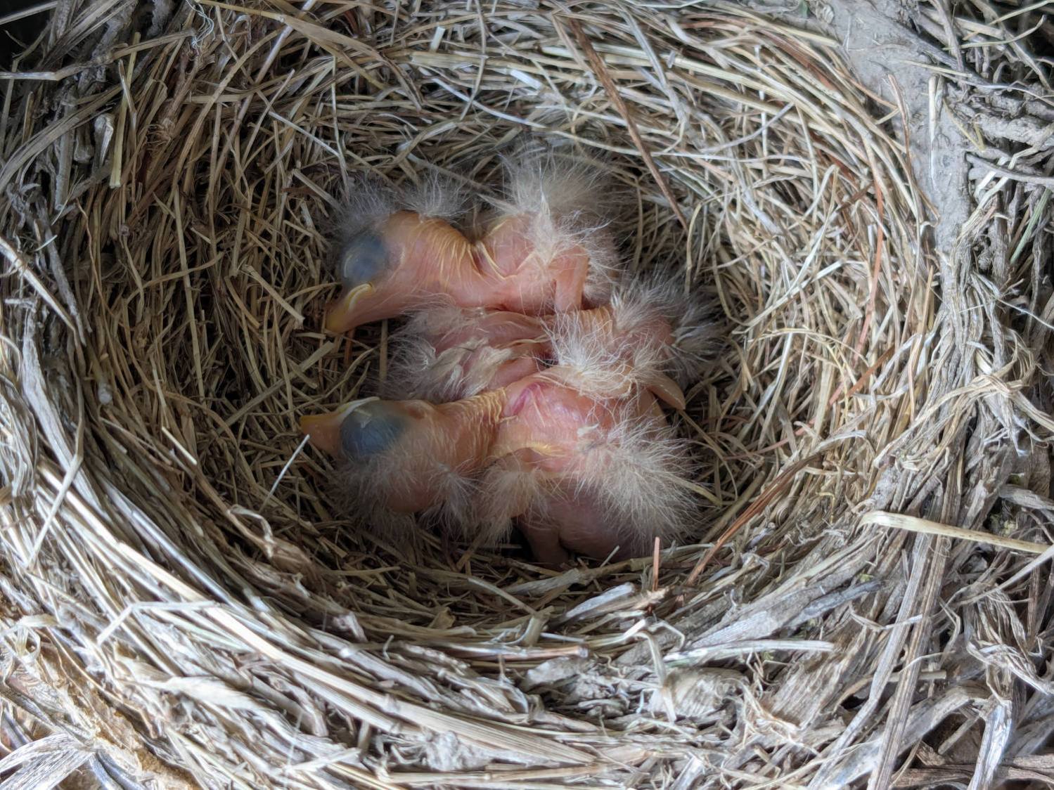
Two weeks later, the first chick pipped:
Wreath Robin Nest – 2025-05-19
Only a mother could love something like that, but they almost always do:
Wreath Robin Nest – 2025-05-20
Floppy chicks are (still) floppy one day later:
Wreath Robin Nest – 2025-05-21
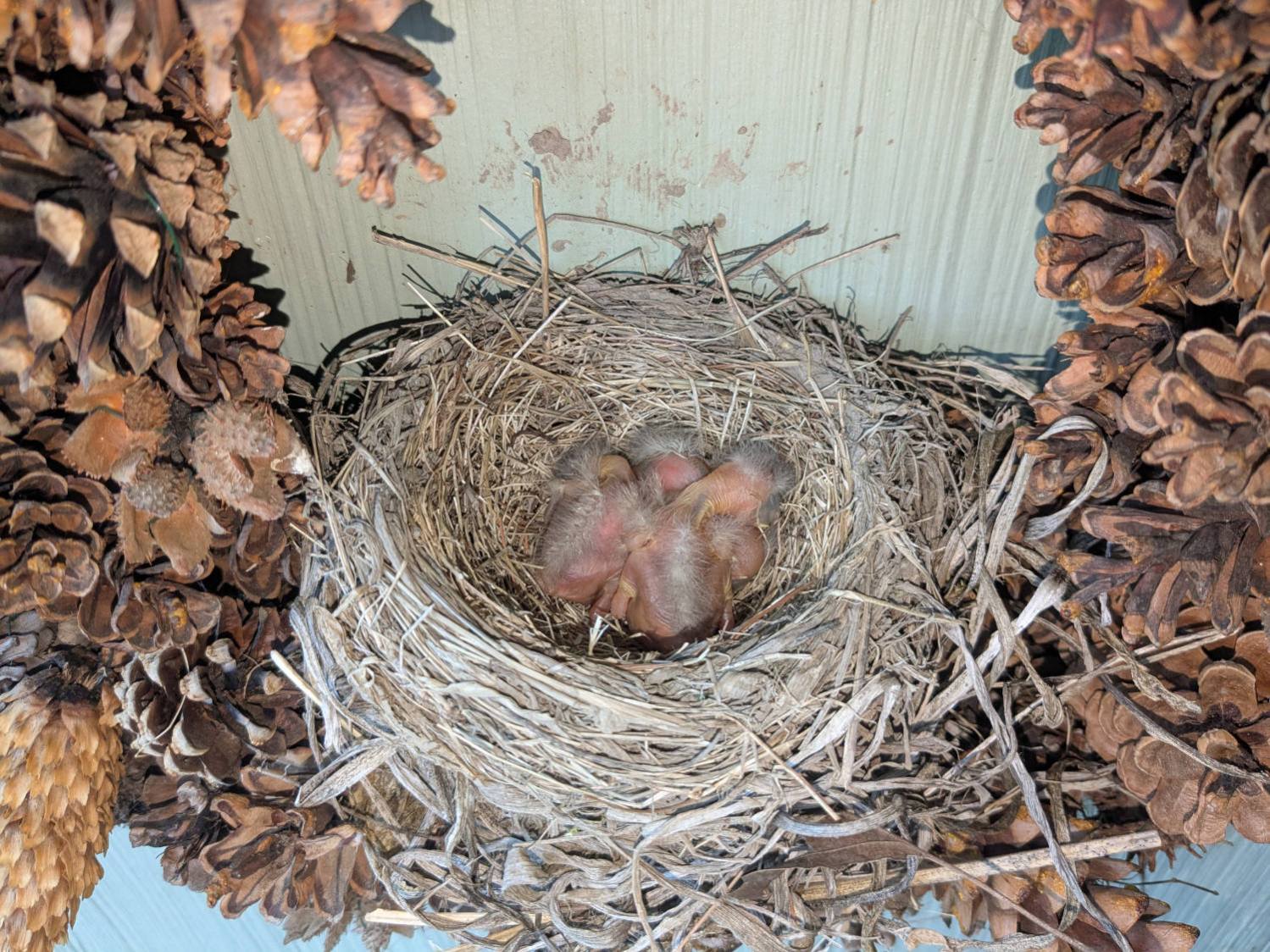
Rapid growth is Job One:
Wreath Robin Nest – 2025-05-22
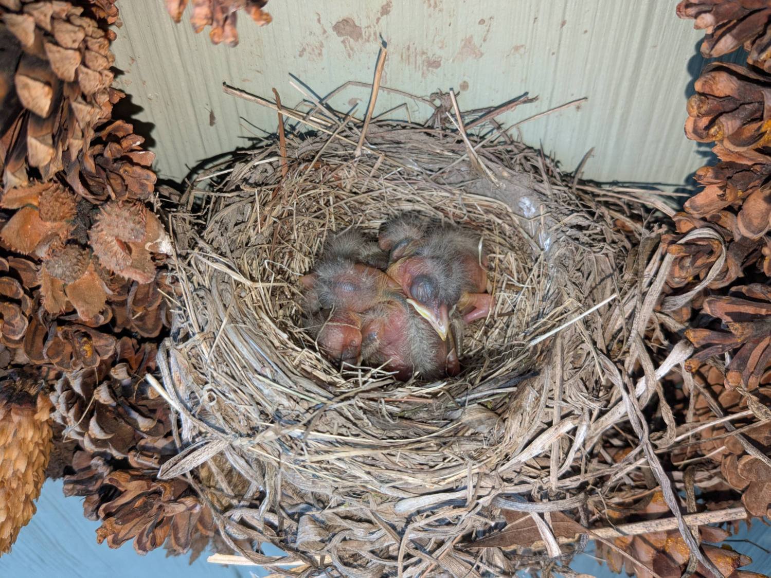
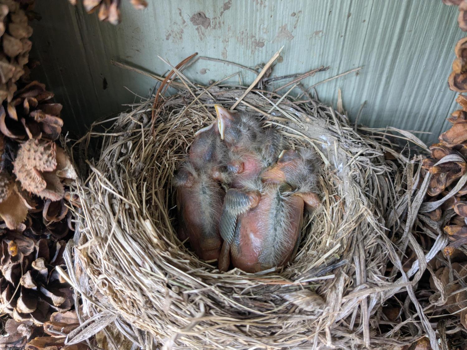
Taking shape:
Wreath Robin Nest – 2025-05-23
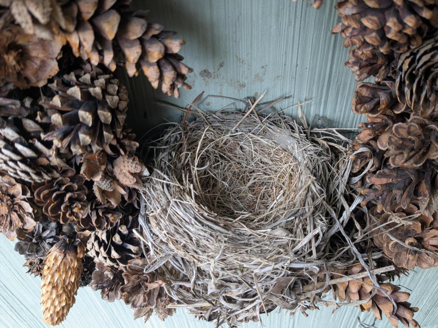
And then there were none:
Wreath Robin Nest – 2025-05-24
The M50 trail camera was defunct, so we don’t know what happened to them. Mary didn’t hear a fuss through the adjacent bedroom window, which suggests something grabbed them while Ms Robin was off getting breakfast.
We took the wreath down and replaced it with a slate plaque, because we’d rather not know …
The power supply converting the battery’s raw 6 V into whatever voltage is required by my troublesome SJCAM M50 trail camera failed, despite the replaced wire between the battery and the camera remaining intact. The camera continued to work with 5 V power supplied through its USB-C jack, so I think it can accomplish most of its goals with a USB battery pack nearby.
Unfortunately, the USB-C jack isn’t accessible with the case closed, so I decided to repurpose the battery compartment’s external 6 V input jack.
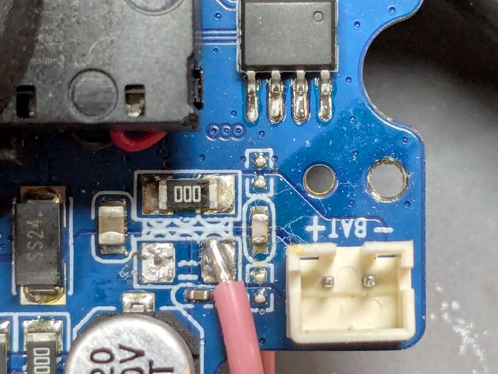
I removed the 000 (0 Ω) SMD “resistor” connecting the battery + terminal to the power supply circuitry and soldered one end of a wire to that pad:
SJCAM M50 – battery input pad
The adjacent 000 “resistor” connects the battery - input terminal to the circuit, so it remains in place.
The other end of the wire goes to the high side of the +5 V filter caps for the USB-C input:
SJCAM M50 – USB power input pad
The battery pack produced 6 V from two parallel-ish banks of four AA cells or an external source arriving through a 3.5 / 1.35 mm coaxial power plug, with a Schottky diode dropping 250 mV before reaching the BAT connector in the first picture. The camera seems happy to run from slightly under 5 V.
Unfortunately, “happy to run” means the camera remains in Setup mode, ready to dump its stored images through the USB port, and won’t take pictures regardless of the switch normally controlling such things. It seems I must either troubleshoot the switching regulator generating the internal power supply voltage(s)or junk the camera.
I’m not red-hot pleased with the several SJCAM cameras I’ve used, as they seem to feature under-designed durability for their intended use. The fact that SJCAM cameras seem to be on the better side of a bad lot is not comforting.
I did the probing & doodling during a Squidwrench remote meeting and was assured I would not regret directly applying five volts to the circuit, said with the intonation of this meme:
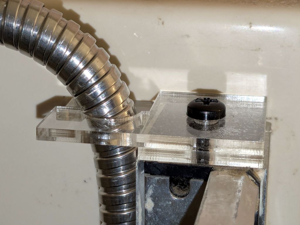
The new shower head’s hose dangled directly in front of the faucet knob, so I conjured a simple clamp to pull the down-going half over to the side of the stall and keep the up-going half away from the faucet:
Shower head hose clamp – installed
The black nylon M6 screw goes into a hole tapped in the plastic cap atop the aluminum extrusion; I was mildly surprised that worked as well as I hoped. It’s basically invisible from outside the shower stall.
Stipulated: laser-cut 3 mm acrylic probably isn’t the right material for the job, but it’s a quick & easy way to discover if that’s the right place to clamp the hose.
While installing those two pieces, it occurred to me the result would be much stronger if the two “jaws” overlapped and had a pair of screws holding them together, so the LightBurn layout includes that idea for the next time:
Shower Head Hose Clamp – LightBurn layout
The Hole Template simplified getting the hole dead center in the plastic cap, because drilling it required an awkward reach across the end of the vanity.
There is zero chance this will fit your shower & hose, but now you have the general idea.
The Basement Shop has 50±5% relative humidity, with the top held down by a hulking dehumidifier (plus a box fan stirring the air) and the bottom supported by being a basement. As a result, the 3D printer filament stabilized at about 50% RH, which seemed to work well enough for PETG.
That’s activated alumina desiccant, mostly because it’s reputed to have more capacity and a lower ultimate humidity than silica gel, but it likely doesn’t make much difference.
In addition to 25 g of desiccant in the PolyDryer meter case, I dropped five teabags holding 10 g each in the bottom of the box for more capacity. I measure the desiccant by putting 75.0 g into a cup, putting 25.0 g in the PolyDryer meter box (aided by a Polydryer Desiccant Funnel), 10.0 g into four teabags, and whatever’s left into the fifth teabag, thus eliminating rounding errors in the smaller quantities.
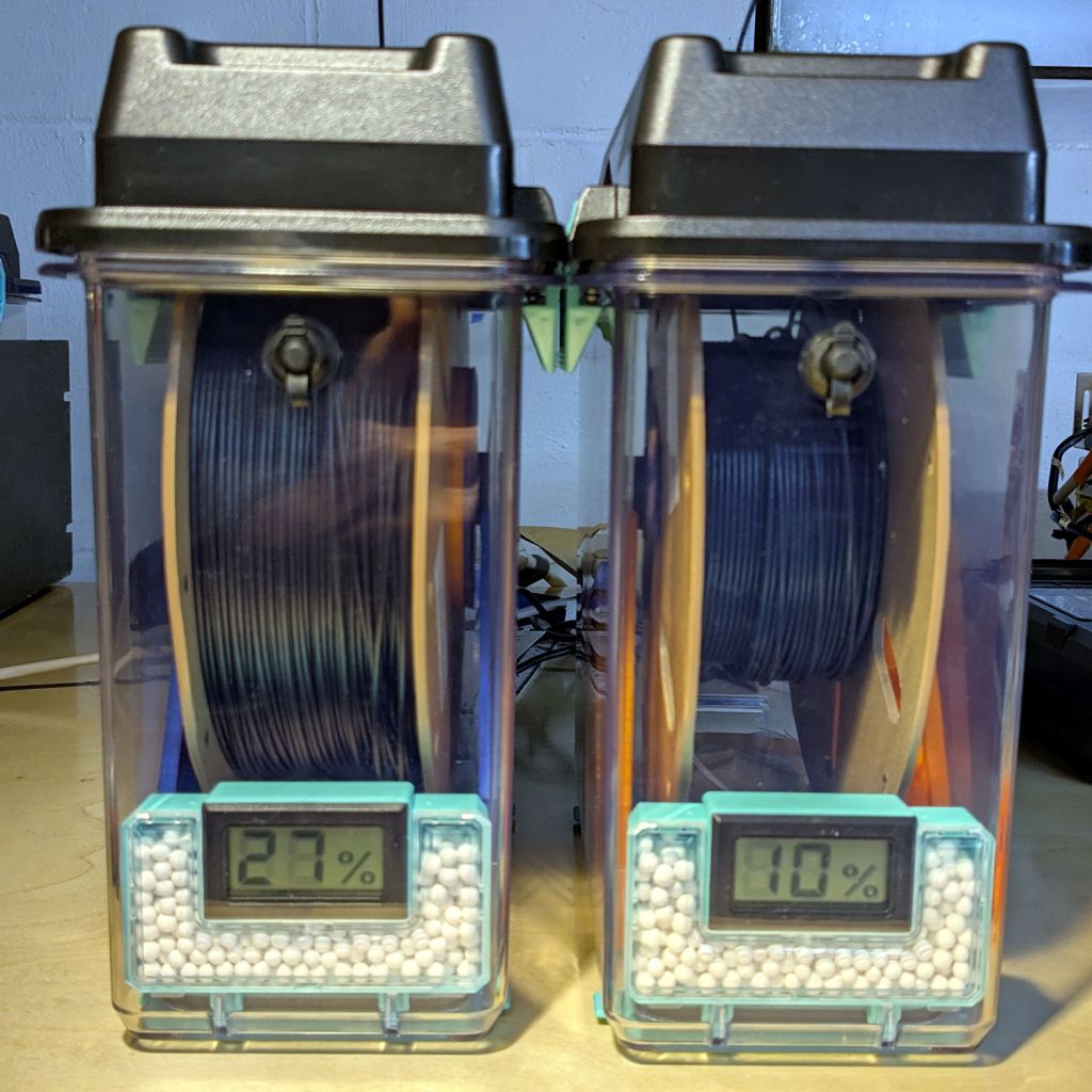
The stabilized humidity inside the boxes seems to depend on the amount of filament on the spool:
Nearly full → 25% to 30% RH
Half full → 20%-ish RH
Nearly empty → 10% to 15% RH
I think the humidity level comes from the filament outgassing water vapor through its (limited) surface area on the outer layer around the spool. The difference between that rate and the desiccant’s ability to remove water vapor from the (unmoving) air in the box sets the stable humidity: more surface area → more water vapor → higher humidity.
After the filament eventually dries out, the humidity should decrease, but diffusion is a slow process. More likely, the humidity will remain stable as the printer pulls filament from the outer layer and exposes the somewhat wetter plastic within.
The heater and fan inside the PolyDryer base unit circulates hot air through the box around the spool, but depends on the desiccant to remove water vapor. Running the base unit for 6 or 12 hours makes little difference in the stabilized humidity, so I think the desiccant is doing the best it can as the filament outgasses more water vapor.
Using Air Exchanger vents seems to make no difference, likely because the desiccant must then pull more water vapor out of the incoming 50% RH basement air. A psychrometric chart says 50% RH air at 60 °F becomes 10% RH air at 120 °F, but moisture in the filament wrapped around the spool can’t escape any faster.
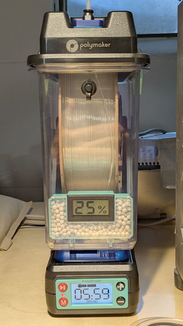
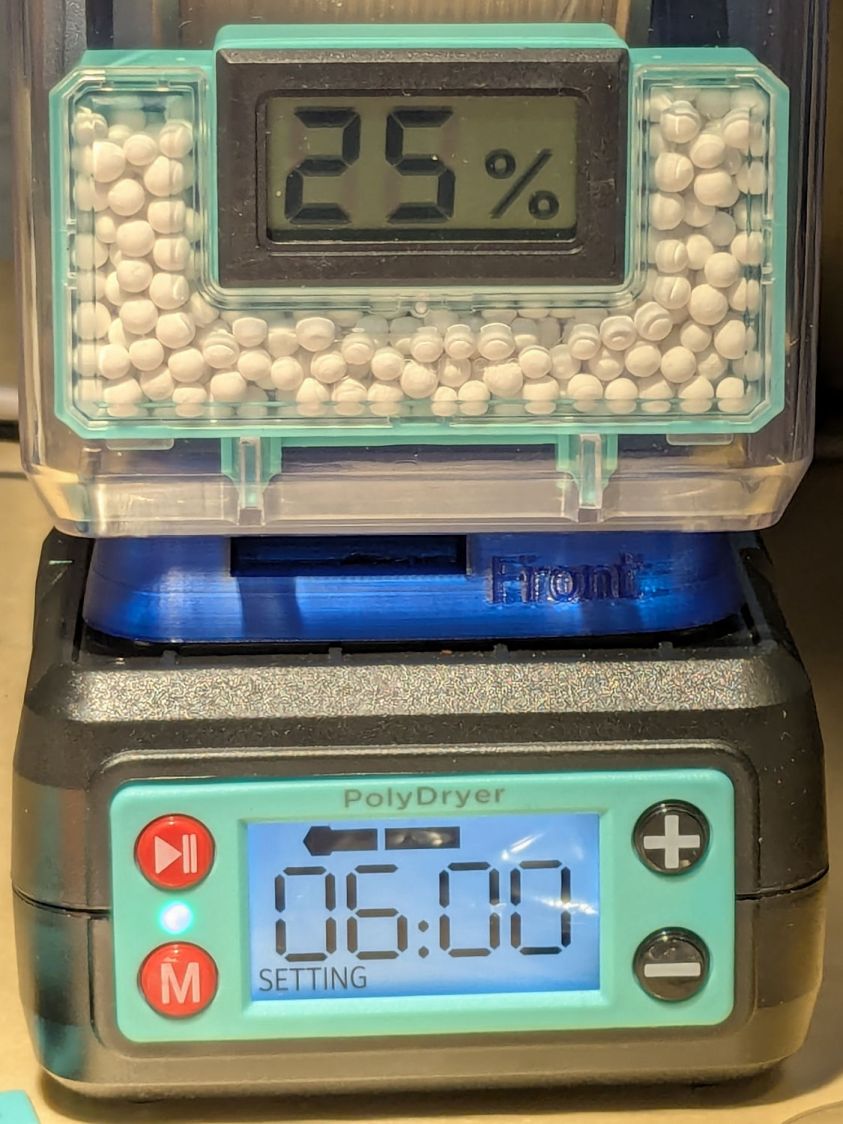
So, for example, a full spool of TPU starting at 25% RH:
PolyDryer humidity – TPU start
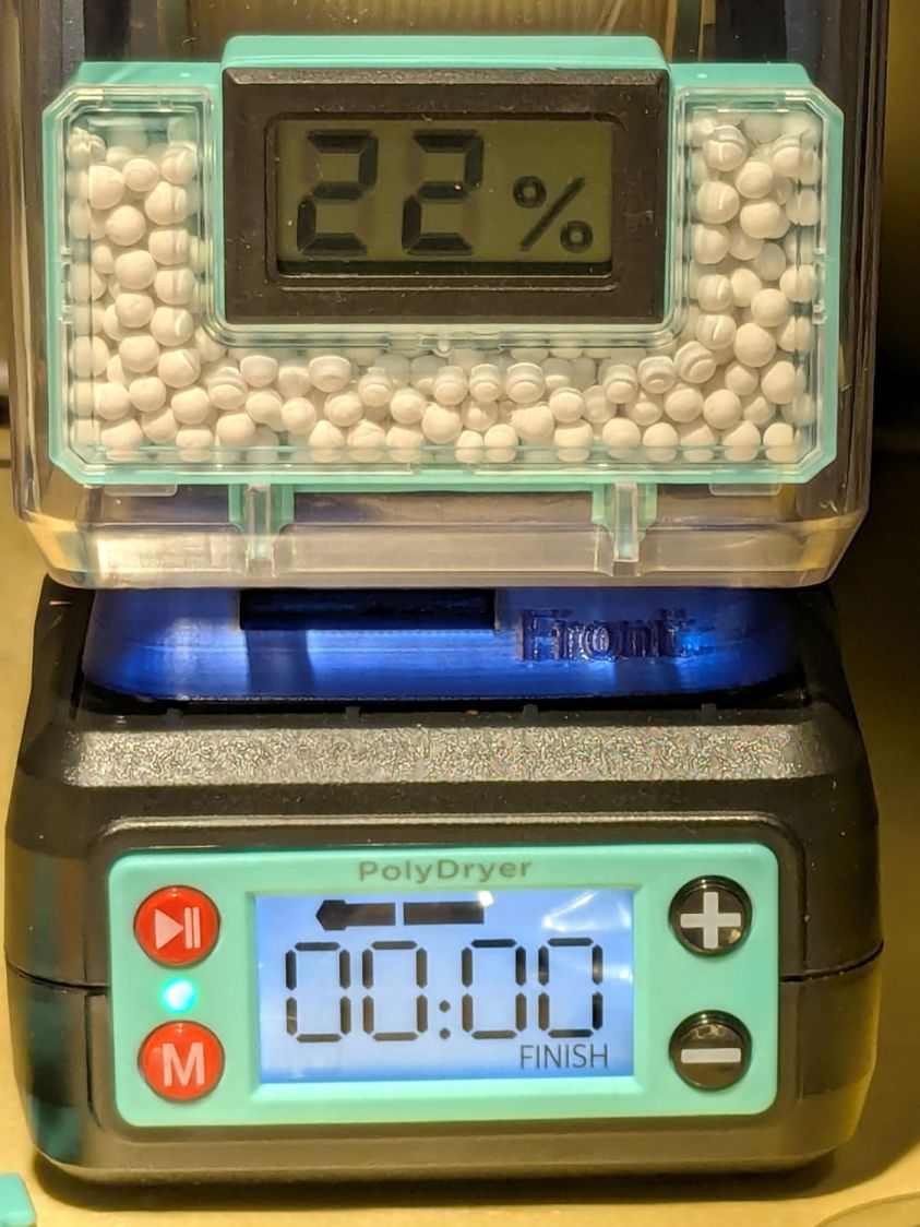
Six hours of drying pulls it down to 22%:
PolyDryer humidity – TPU finish
After sitting overnight it’s back at 25%:
PolyDryer humidity – TPU after 14 hr
Admittedly, that was with the vents in place, but the closed box started at 25% RH after sitting around for a week or so following a similar drying cycle.
The desiccant had absorbed 4 g of water since I put it in, so it hasn’t been entirely idle.
Which suggests 75 g of activated alumina desiccant is workin’ hard and doin’ swell in there, with the filament acting as an essentially infinite reservoir of water vapor.
I haven’t noticed any particular difference in PETG print quality and the TPU hasn’t gotten enough mileage to notice much trouble, but reducing the MMU3 buffer clutter was totally worth the effort.
We don’t know what the proper term might be for this part of the machine, but it looks sorta like a nose and the lights form most of a ring around it, so I’m going with “Nose Ring Lights”:
Handi-Quilter sells a ring light for machines manufactured a decade later than ours, but it uses a built-in USB jack this machine lacks.
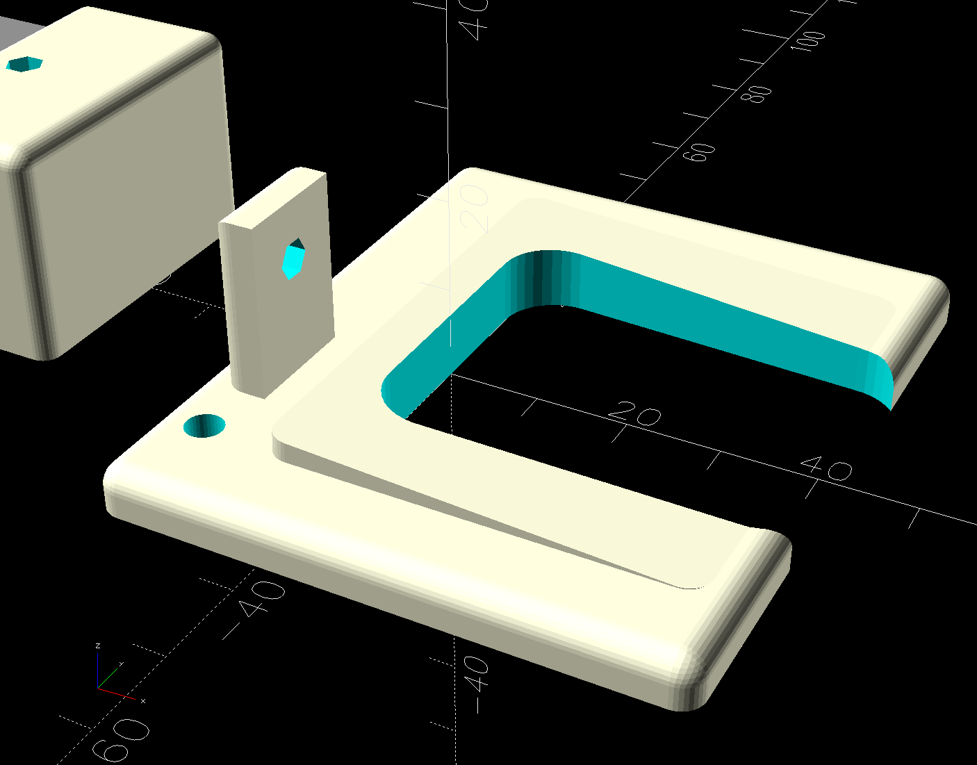
One of two (apparently) unused M4 holes on the left side of the machine frame suggested a mounting point for a 3D printed bracket:
HQ Sixteen Nose Ring Lights – solid model
The ramp matches the 3° (-ish) mold draft of the machine frame, which I initially ignored by angling the tab, but a tilted frame looked awful; it’s now aligned with local horizontal..
A few iterations got all the pieces & holes in their proper places:
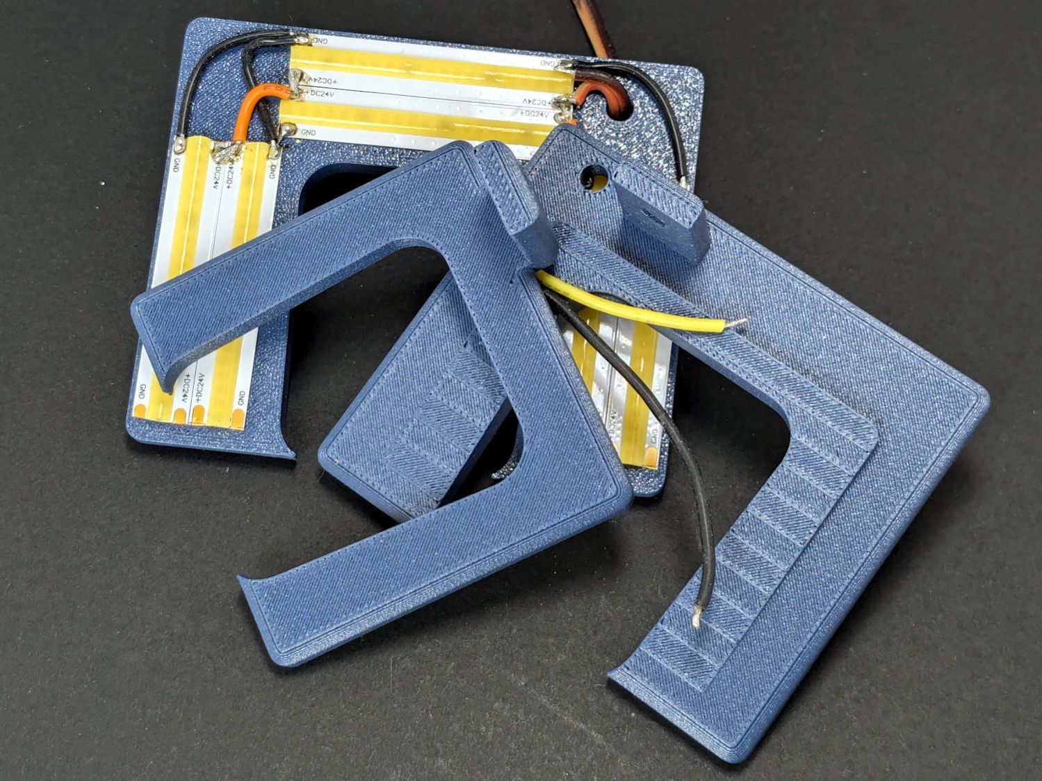
HQ Sixteen Nose Ring lights – iterations
The smaller (rampless) bracket has three LED strips, but a quick test showed more light would be better:
HQ Sixteen Nose Ring lights – bottom view
The lack of a transparent-ish cover is obviously unsuitable for a commercial product, but the key design goal is to not interfere with spreading as much light as possible across as much of the quilt as possible. The black JB Weld Plastic Bonder blobs keep the 24 VDC supply out of harm’s way, which is as good as it needs to be for now.
The bracket has three sides, because the right side of the machine has all the thread guide hardware. Putting anything over there seemed likely to interfere with either thread movement or fingers making adjustments.
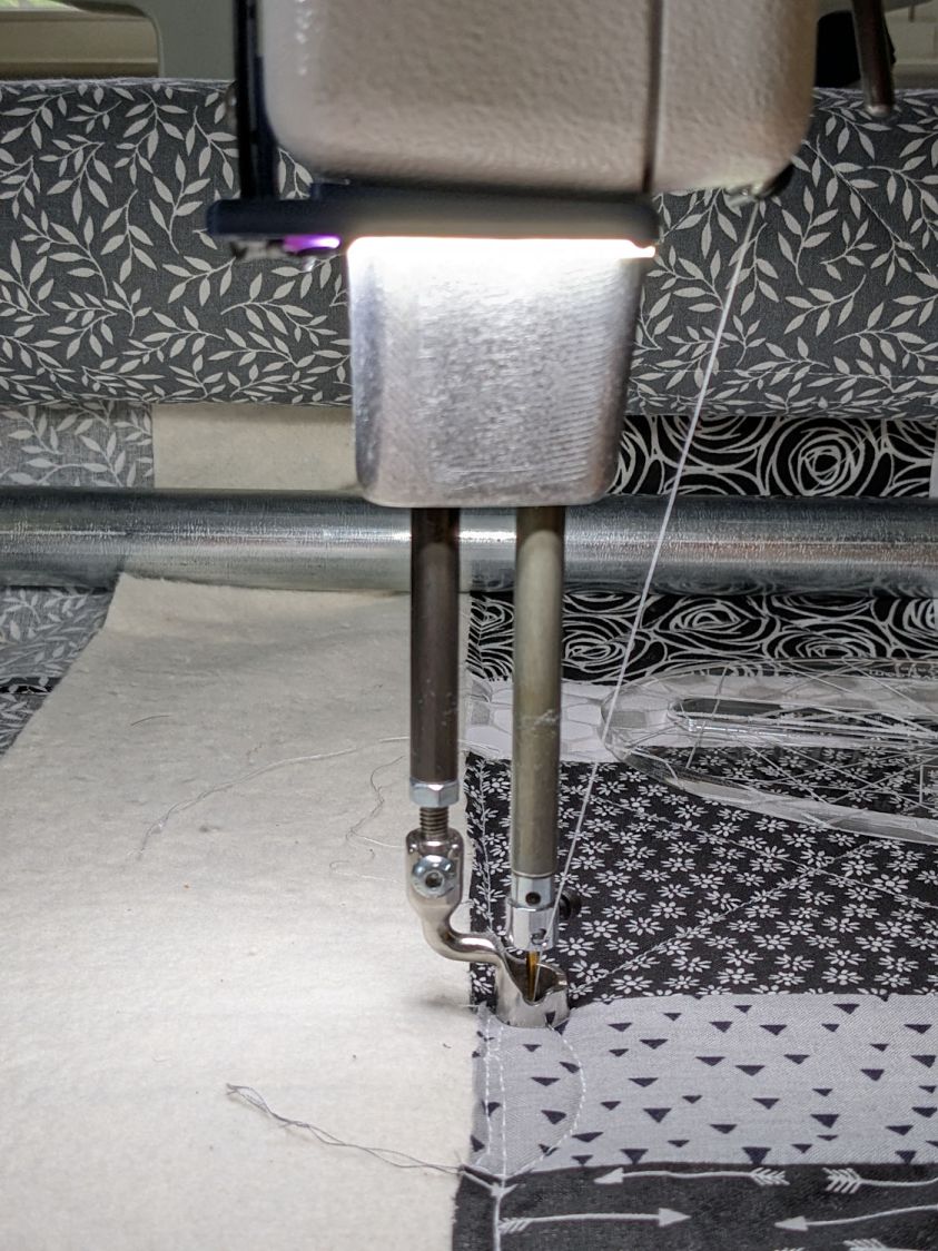
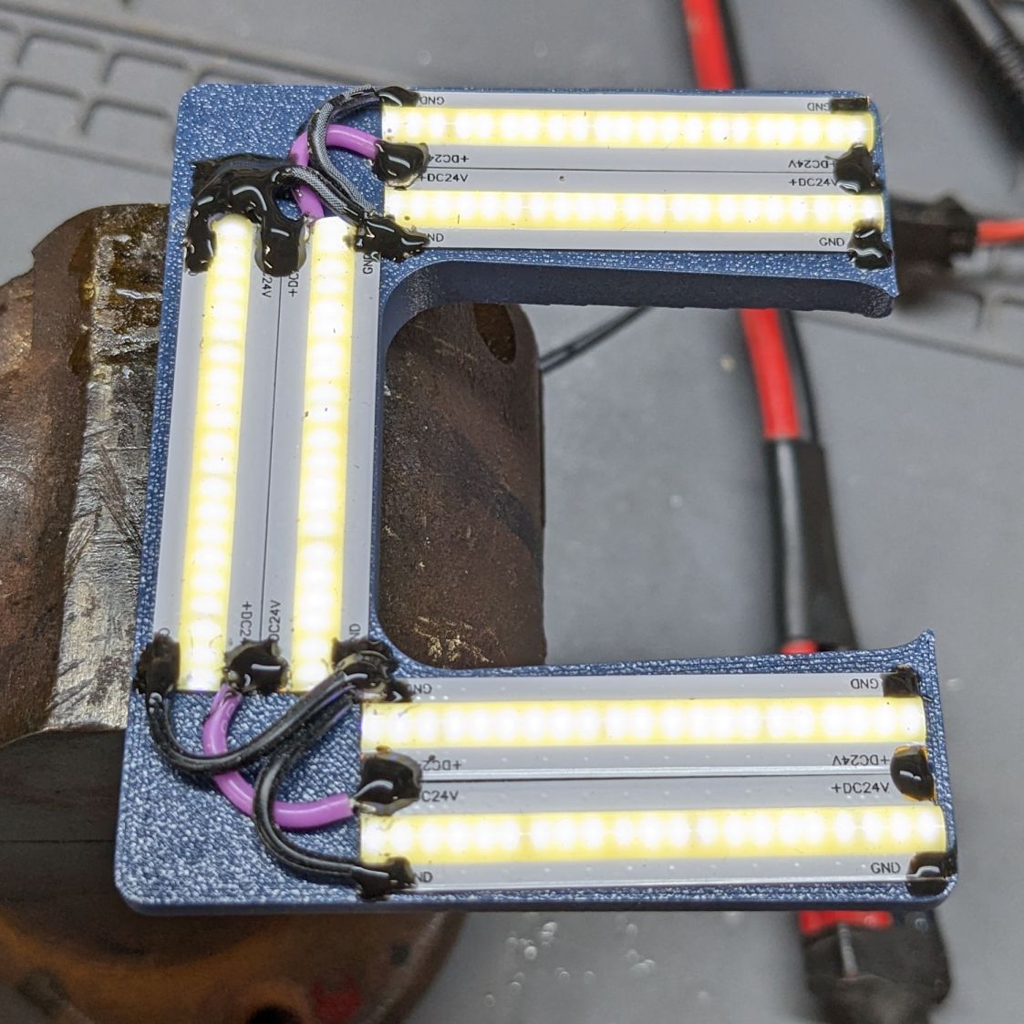
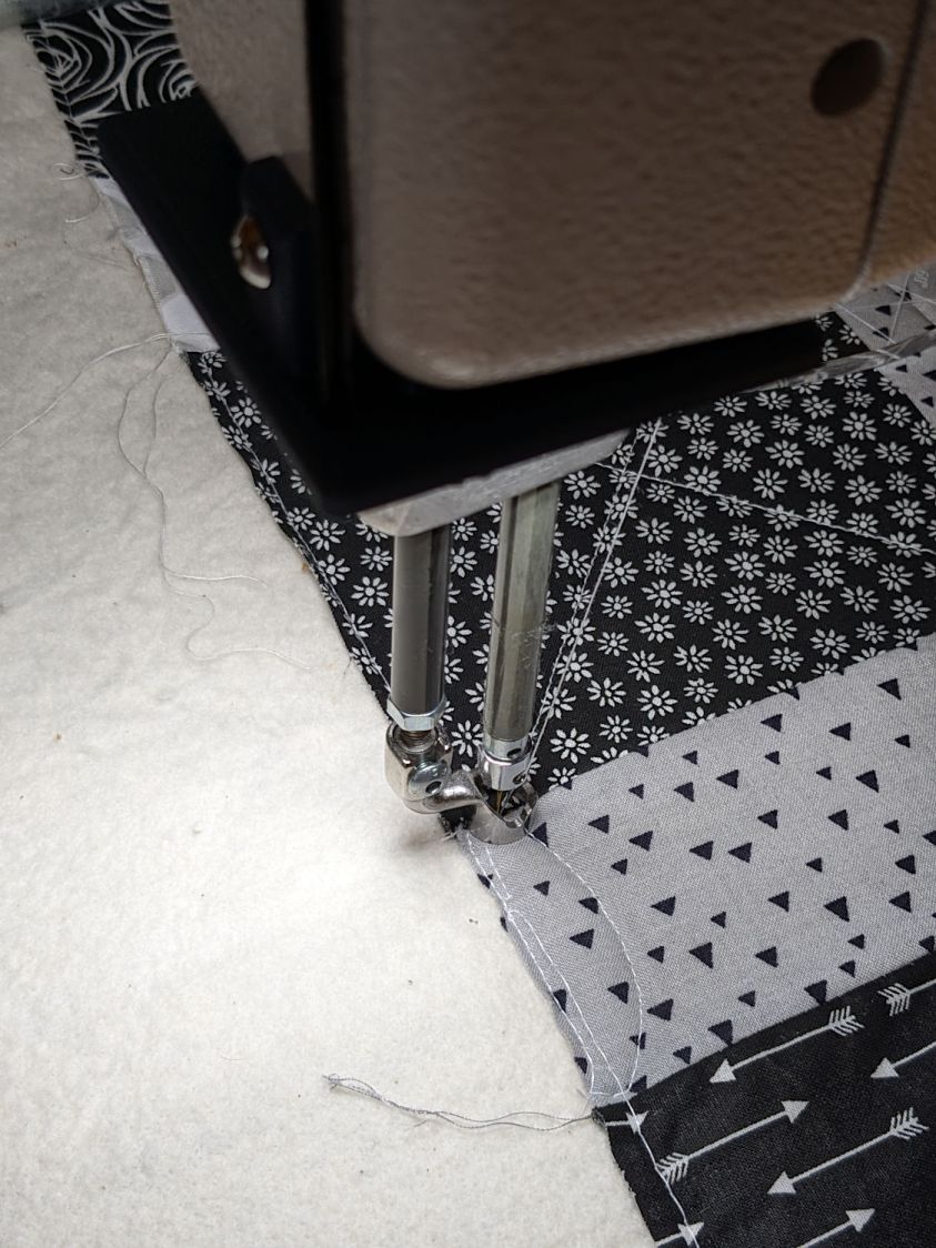
Fortunately, the wider bracket doesn’t stick out too far beyond the machine frame and the doubled LED strips create a much smoother light pool:
HQ Sixteen Nose Ring lights – left front view
Yes, the quilt is focused and the LED frame is blurred.
The larger light-emitting area reduces the shadow under the left rod (supporting the ruler foot) enough to be unobjectionable.
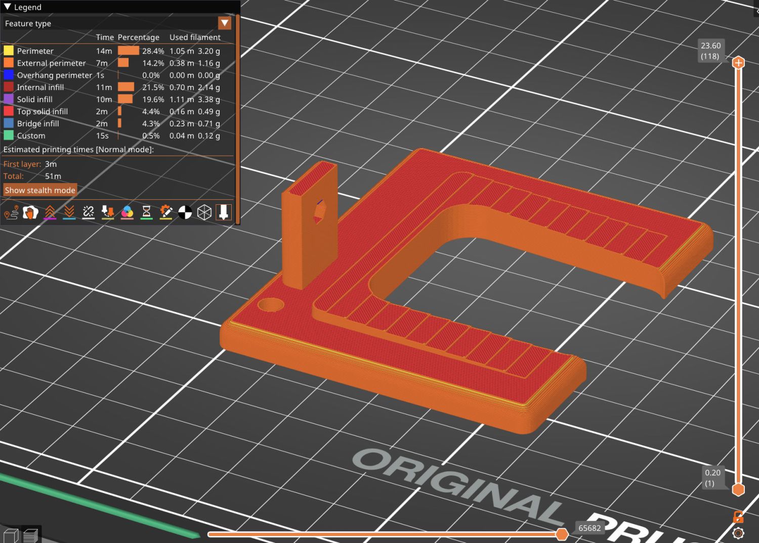
A 0.2 mm layer thickness transforms the smooth ramp into stair steps:
HQ Sixteen Nose Ring Lights – PrusaSlicer
They’re inconspicuous after the bracket is installed.
The Chin Light ran on 12 V and these strips require 24 V, so the OpenSCAD code creates a pair of endcaps for the new supply, which is of course completely different than the old supply. Setting that up must await quilt completion.
This file contains hidden or bidirectional Unicode text that may be interpreted or compiled differently than what appears below. To review, open the file in an editor that reveals hidden Unicode characters.
Learn more about bidirectional Unicode characters