|
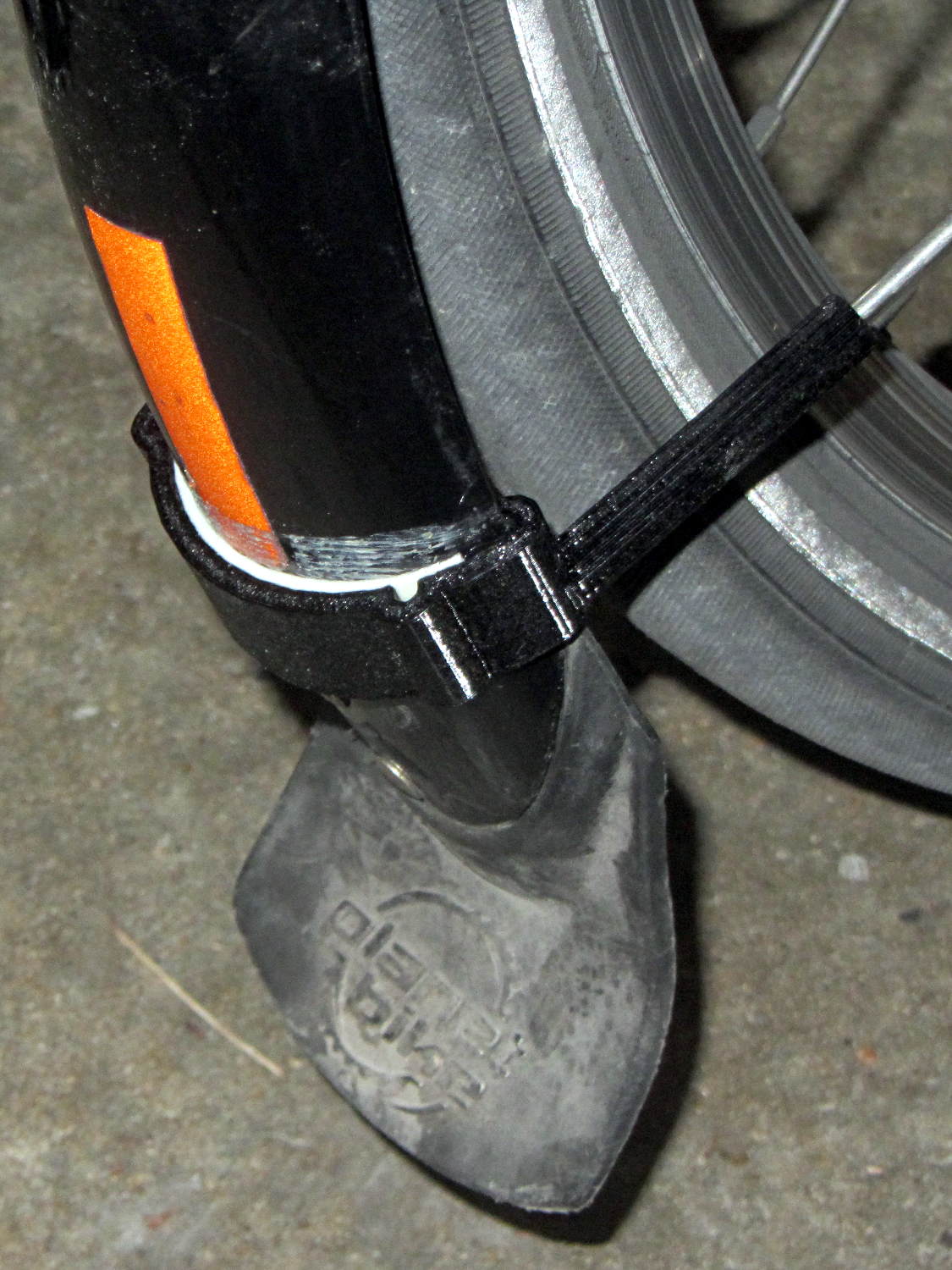
// Badge Lanyard Reel Mount |
|
// Ed Nisley KE4ZNU April 2017 |
|
// Reel center at origin, lanyard exit toward +X |
|
|
|
Layout = "Show"; |
|
|
|
Support = true; |
|
|
|
//- Extrusion parameters must match reality! |
|
|
|
ThreadThick = 0.20; |
|
ThreadWidth = 0.40; |
|
|
|
HoleWindage = 0.2; |
|
|
|
Protrusion = 0.05; // make holes end cleanly |
|
|
|
inch = 25.4; |
|
|
|
function IntegerMultiple(Size,Unit) = Unit * ceil(Size / Unit); |
|
|
|
//———————- |
|
// Dimensions |
|
|
|
ID = 0; // for round things |
|
OD = 1; |
|
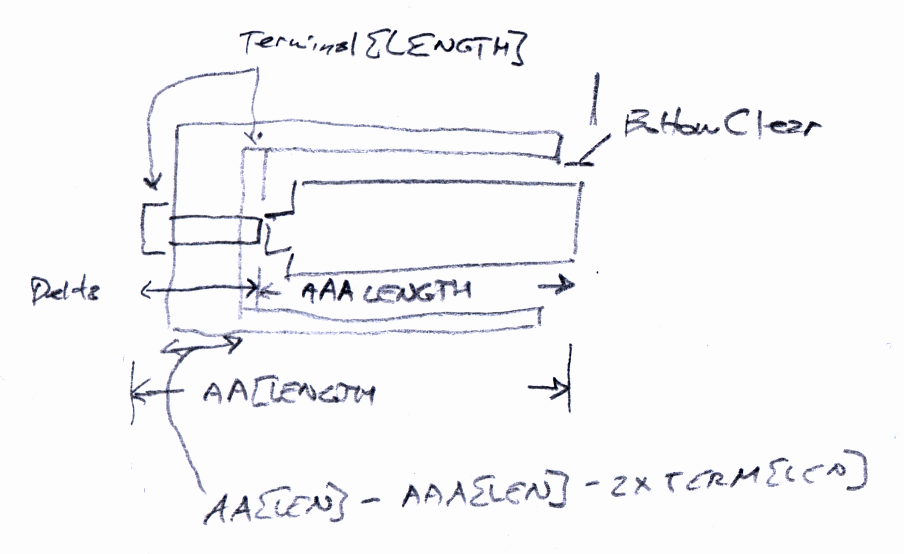
LENGTH = 2; |
|
|
|
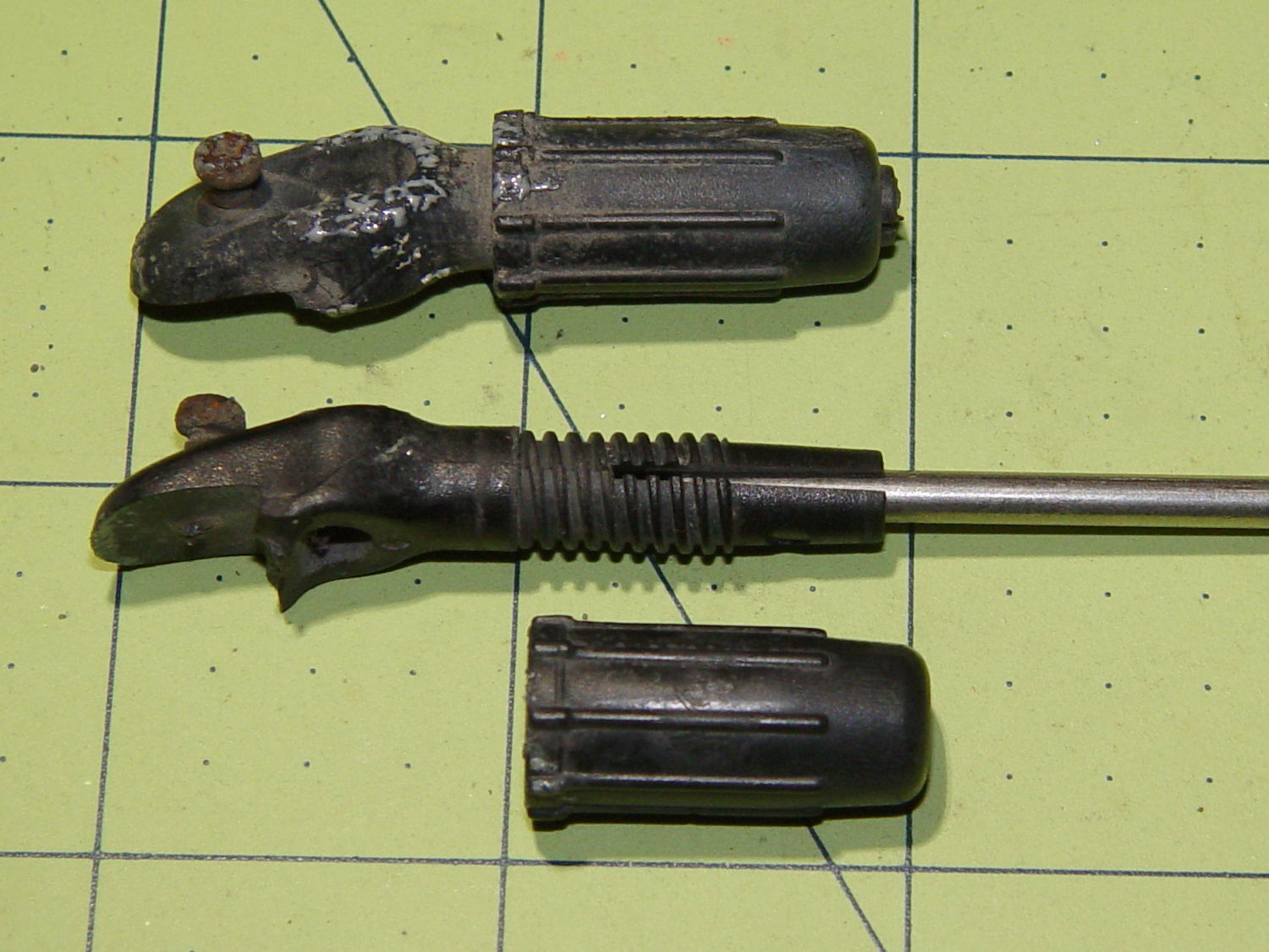
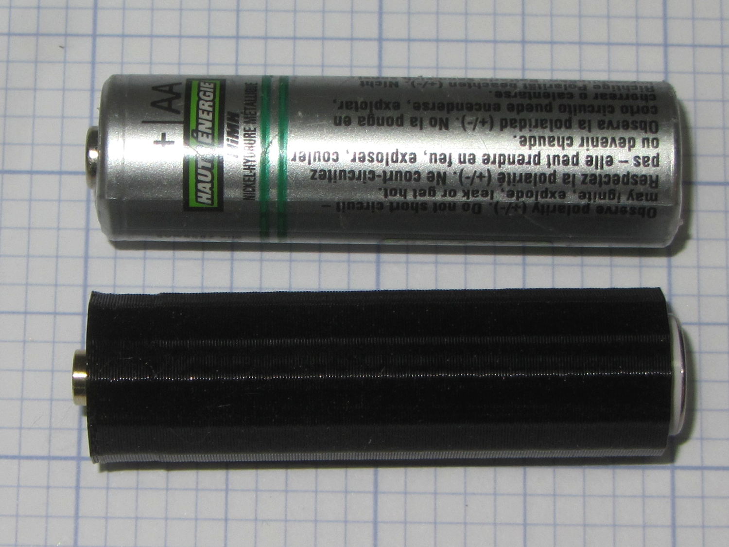
Carabiner = [30.7,35.3,3.5]; // metal carabiner around original reel |
|
Latch = [6.0,-15,8.0]; // wire spring latch: offset from OD + thickness |
|
LatchAngle = 60; // max deflection angle to center from -X direction |
|
|
|
LatchPoints = [[0,0], |
|
[Latch[1]/tan(LatchAngle),0], |
|
[Latch[1]/tan(LatchAngle),-Latch[1]]]; // polygon in as-cut orientation |
|
|
|
echo(str("Latch polygon: ",LatchPoints)); |
|
|
|
Screw = [2.0,3.8 + 0*ThreadWidth,10.0]; // M2 screw: ID = clear, OD = head |
|
ScrewHeadLength = 2.0; |
|
ScrewSides = 8; |
|
ScrewRecess = 5*ThreadThick; |
|
|
|
MountSides = ScrewSides; // suitably gritty corners |
|
|
|
MountThick = Screw[LENGTH] / cos(180/MountSides) + ScrewRecess + 2.0; |
|
|
|
Insert = [Screw[ID],3.4,4.0]; // brass insert for screws |
|
|
|
BCD = Carabiner[OD] + 2.5*Insert[OD]; |
|
|
|
BoltAngles = [20,110]; // ± angles to bolt holes |
|
|
|
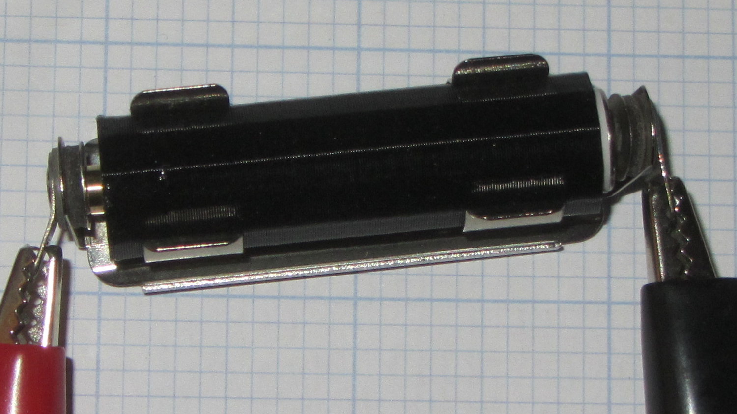
Reel = [5.3,25.5 + 2*ThreadWidth,6.0 + 2*ThreadThick]; // lanyard cord reel |
|
ShimThick = 2*ThreadThick; // covers open side of reel for better sliding |
|
|
|
Bezel = [31.0,32.0,7.5]; // PCB holder + shell, LENGTH = post + shell |
|
BezelSides = 6*4; |
|
BezelBlock = [5.5,7.5,3.6] + [ThreadWidth,ThreadWidth,ThreadThick]; // block around lanyard eyelet |
|
|
|
Eyelet = [3.5,4.5,3.0]; |
|
|
|
Bullet = [2.0,6.5,2.0]; // brass badge holder, LENGTH = recess into mount |
|
|
|
//———————- |
|
// Useful routines |
|
|
|
module PolyCyl(Dia,Height,ForceSides=0) { // based on nophead's polyholes |
|
|
|
Sides = (ForceSides != 0) ? ForceSides : (ceil(Dia) + 2); |
|
|
|
FixDia = Dia / cos(180/Sides); |
|
|
|
cylinder(r=(FixDia + HoleWindage)/2, |
|
h=Height, |
|
$fn=Sides); |
|
} |
|
|
|
//– Lanyard reel mockup |
|
|
|
module Reel() { |
|
|
|
cylinder(d=Reel[OD],h=Reel[LENGTH],center=true,$fn=6*4); |
|
|
|
} |
|
|
|
// Carabiner metal mockup |
|
// Some magic numbers lie in wait |
|
|
|
module Beener() { |
|
|
|
difference() { |
|
hull() { |
|
cylinder(d=Carabiner[OD], |
|
h=Carabiner[LENGTH] + 2*ThreadThick, |
|
center=true,$fn=BezelSides); |
|
translate([-Carabiner[OD]/2,0,0]) |
|
cylinder(d=Carabiner[OD] – 2.0, |
|
h=Carabiner[LENGTH] + 2*ThreadThick, |
|
center=true,$fn=6*4); |
|
} |
|
cylinder(d=Carabiner[ID], |
|
h=2*Carabiner[LENGTH], |
|
center=true,$fn=BezelSides); |
|
translate([Carabiner[ID]/4,0,0]) |
|
cube([Carabiner[ID],7.0,2*Carabiner[LENGTH]],center=true); |
|
} |
|
} |
|
|
|
// mockup of PCB holder atop remains of old mount with reel post |
|
// Z = 0 at midline of case |
|
|
|
module BezelMount() { |
|
|
|
rotate(180/BezelSides) { |
|
PolyCyl(Bezel[ID] + HoleWindage,MountThick,BezelSides); // PCB punches through mount |
|
PolyCyl(Bezel[OD] + HoleWindage,Bezel[LENGTH] – Reel[LENGTH]/2,BezelSides); |
|
} |
|
|
|
translate([Reel[OD]/2,0,BezelBlock[2]/2]) |
|
scale([2,1,1]) |
|
cube(BezelBlock,center=true); |
|
} |
|
|
|
// Main mount around holder & carabiner |
|
|
|
module Mount(Section="All") { |
|
|
|
render() |
|
difference() { |
|
hull() { |
|
for (a = BoltAngles) // spheres defining corners |
|
for (i=[-1,1]) |
|
rotate(i*a) |
|
translate([BCD/2,0,0]) |
|
sphere(d=MountThick,$fn=MountSides); |
|
cylinder(d=Carabiner[OD] + 4*ThreadWidth, |
|
h=MountThick,center=true); // capture carabiner ring |
|
} |
|
|
|
for (a = BoltAngles) // screw & insert holes, head recess |
|
for (i=[-1,1]) |
|
rotate(i*a) |
|
translate([BCD/2,0,0]) |
|
rotate(0*i*180/ScrewSides) { |
|
translate([0,0,-(Insert[LENGTH] + 2*ThreadThick)]) |
|
PolyCyl(Insert[OD], |
|
Insert[LENGTH] + 2*ThreadThick + Protrusion,ScrewSides); |
|
for (k = [-2:2]) // epoxy retaining grooves |
|
translate([0,0,-(k*3*ThreadThick + Insert[LENGTH]/2)]) |
|
PolyCyl(Insert[OD] + 1*ThreadWidth, |
|
2*ThreadThick,ScrewSides); |
|
PolyCyl(Screw[ID],Screw[LENGTH],ScrewSides); |
|
translate([0,0,MountThick/2 – ScrewRecess]) // recess screw heads |
|
PolyCyl(Screw[OD],Screw[LENGTH],ScrewSides); |
|
} |
|
|
|
translate([0,0,-1*ThreadThick]) // Minkowski Z extends only top surface! |
|
minkowski() { // space for metal carabiner |
|
Beener(); |
|
// cube([ThreadWidth,ThreadWidth,2*ThreadThick]); |
|
cylinder(d=ThreadWidth,h=2*ThreadThick,$fn=6); |
|
} |
|
|
|
rotate([0,90,0]) rotate(180/6) // cord channel = brass tube clearance |
|
PolyCyl(Bullet[ID],Carabiner[ID],6); |
|
|
|
translate([Eyelet[LENGTH] + 2.0,0,0]) // eyelet, large end inward |
|
rotate([0,90,0]) rotate(180/6) |
|
PolyCyl(Eyelet[OD] + HoleWindage, Reel[OD]/2,6); |
|
|
|
if (false) |
|
translate([Reel[OD]/2 + Eyelet[LENGTH]/2,0,0]) // eyelet, small end outward |
|
rotate([0,90,0]) rotate(180/6) |
|
PolyCyl(Eyelet[ID],Eyelet[LENGTH],6); |
|
|
|
translate([(BCD/2 + MountThick/2)*cos(BoltAngles[0]) – Bullet[LENGTH],0,0]) // bullet recess |
|
rotate([0,90,0]) rotate(180/6) |
|
PolyCyl(Bullet[OD],Carabiner[ID],6); |
|
|
|
BezelMount(); // PCB holder clearance |
|
|
|
Reel(); // reel clearance |
|
|
|
translate([0,0,-(Reel[LENGTH] + ShimThick)/2]) // sliding plate on open side of reel |
|
cylinder(d=Reel[OD],h=ShimThick,center=true,$fn=6*4); |
|
|
|
translate([-Carabiner[OD]/2 + Latch[0],Latch[1],0]) |
|
linear_extrude(height=Latch[2],center=true) |
|
polygon(LatchPoints); |
|
|
|
if (Section == "Upper") // display & build section cutting |
|
translate([0,0,-2*Carabiner[LENGTH]]) |
|
cube(4*Carabiner,center=true); |
|
else if (Section == "Lower") |
|
translate([0,0,2*Carabiner[LENGTH]]) |
|
cube(4*Carabiner,center=true); |
|
|
|
} |
|
|
|
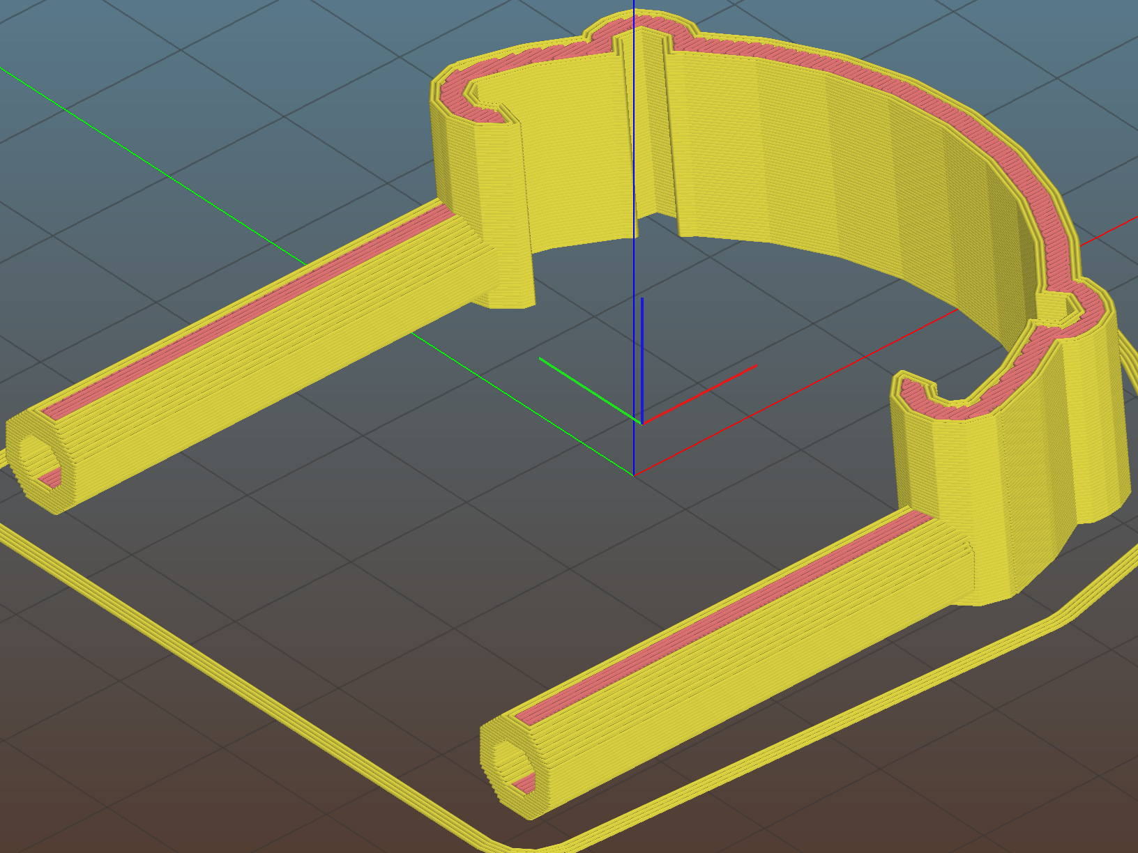
if (Support) { // Completely ad-hoc support structures |
|
color("Yellow", Layout == "Show" ? 0.3 : 1.0) { |
|
if (false && Section == "Upper") { |
|
Spokes = BezelSides; |
|
Offset = 6*ThreadWidth; |
|
for (i = [2:Spokes – 2]) |
|
rotate(i * 360/Spokes) |
|
translate([Offset,-ThreadWidth,0*(Carabiner[LENGTH]/2)/2]) |
|
cube([Carabiner[OD]/2 – Offset – 0*ThreadWidth, |
|
2*ThreadWidth, |
|
Carabiner[LENGTH]/2],center=false); |
|
for (i = [0:Spokes – 1]) |
|
rotate(i * 360/Spokes) |
|
translate([Offset,-ThreadWidth,0]) |
|
cube([Bezel[OD]/2 – Offset, |
|
2*ThreadWidth, |
|
Bezel[LENGTH] – Reel[LENGTH]/2 – 2*ThreadThick],center=false); |
|
Bars = 7; |
|
render() |
|
difference() { |
|
union() { |
|
for (i = [-floor(Bars/2) : floor(Bars/2)]) |
|
translate([-Carabiner[ID]/2,i*Carabiner[OD]/Bars,Carabiner[LENGTH]/4]) |
|
cube([Carabiner[ID]/3,2*ThreadWidth,Carabiner[LENGTH]/2],center=true); |
|
translate([-Carabiner[ID]/2,0,ThreadThick/2]) |
|
cube([Carabiner[ID]/3,Carabiner[ID],ThreadThick],center=true); |
|
} |
|
cylinder(d=Carabiner[ID] + 2*ThreadWidth,h=Carabiner[LENGTH]); |
|
} |
|
} |
|
if (Section == "Lower") { |
|
translate([0,0,-(Reel[LENGTH]/4 + ShimThick/2 – ThreadThick/2)]) |
|
for (i = [0:8]) |
|
rotate(i * 360/8) |
|
cube([Reel[OD] – 2*ThreadWidth, |
|
2*ThreadWidth, |
|
Reel[LENGTH]/2 + ShimThick – ThreadThick],center=true); |
|
if (false) { |
|
Bars = 7; |
|
render() |
|
difference() { |
|
union() { |
|
for (i = [-floor(Bars/2) : floor(Bars/2)]) |
|
translate([-Carabiner[ID]/2,i*Carabiner[OD]/Bars,-Carabiner[LENGTH]/4]) |
|
cube([Carabiner[ID]/3,2*ThreadWidth,Carabiner[LENGTH]/2],center=true); |
|
translate([-Carabiner[ID]/2,0,-ThreadThick/2]) |
|
cube([Carabiner[ID]/3,Carabiner[ID],ThreadThick],center=true); |
|
} |
|
translate([0,0,-Carabiner[LENGTH]]) |
|
cylinder(d=Carabiner[ID] + 0*ThreadWidth,h=Carabiner[LENGTH]); |
|
} |
|
} |
|
} |
|
} |
|
} |
|
|
|
} |
|
|
|
|
|
|
|
//———————- |
|
// Build it |
|
|
|
if (Layout == "Beener") |
|
Beener(); |
|
|
|
if (Layout == "Mount") |
|
Mount(); |
|
|
|
if (Layout == "Reel") |
|
Reel(); |
|
|
|
if (Layout == "BezelMount") |
|
BezelMount(); |
|
|
|
Gap = 25; |
|
if (Layout == "Show") { |
|
translate([0,0,Gap/2]) |
|
Mount("Upper"); |
|
translate([0,0,-Gap/2]) |
|
Mount("Lower"); |
|
color("Green",0.3) |
|
Beener(); |
|
color("Brown",0.3) |
|
Reel(); |
|
color("Red",0.3) |
|
translate([0,0,-(Reel[LENGTH] + ShimThick)/2]) |
|
cylinder(d=Reel[OD],h=ShimThick,center=true,$fn=6*4); |
|
} |
|
|
|
if (Layout == "Build") { |
|
translate([(BCD + MountThick)/2,0,0]) |
|
rotate(180) |
|
Mount("Upper"); |
|
rotate([180,0,0]) |
|
translate([-(BCD + MountThick)/2,0,0]) |
|
Mount("Lower"); |
|
} |
|
|
|
if (Layout == "BuildUpper") |
|
Mount("Upper"); |
|
|
|
if (Layout == "BuildLower") |
|
rotate([180,0,0]) |
|
Mount("Lower"); |