Measured from the Official PCB Layout, with the board origin at the lower-left corner of the PCB, down there by the D9 pin, in mils (0.001 inch):
- D9 = (50,50)
- D10 = (650,50)
- A5 = (535,805)
- A4 = (535,705)
- A7 = (535,393)
- A6 = (535,293)
- FTDI header = (100,1250) to (600,1250)
- Reset button = (350,105)
- D13 LED = (540,100)
- PWR LED = (350,850)
- Upper fiducial = (160,1140)
- Lower fiducial = (490,100)
Subtract 50 mils from each of those coordinates to put the origin at the middle of the D9 pin, which may be more useful. Doing that in inches produces:
- D9 = (0.000,0.000)
- D10 = (0.600,0.000)
- A5 = (0.485,0.755)
- A4 = (0.485,0.655)
- A7 = (0.485,0.343)
- A6 = (0.485,0.243)
- FTDI header = (0.050,1.200) to (0.550,1.200)
- Reset button = (0.300,0.055)
- D13 LED = (0.490,0.050)
- PWR LED = (0.300,0.800)
- Upper fiducial = (0.110,1.090)
- Lower fiducial = (0.440,0.050)
Trust, but verify…
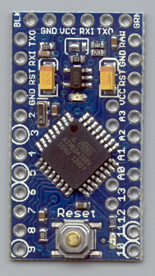
Yes, this is a knockoff PCB from the usual eBay vendor, not from Sparkfun. Contents may settle during shipment. Enlarged to show texture. Your mileage may vary. No warranty, either express or implied, no lie. Do not eat.

Comments
5 responses to “Arduino Pro Mini Pin Coordinates”
I was just doing this exercise with a Teensy 2.0, but for PCB layout. Turns out its pins are all on 0.1″ centers, but there are a couple of I/O pins tucked inside the perimeter. Since I’m building a 24-channel dimmers, I need all 25 of ’em (the 25th one is for the zero crossing input for phase control).
There seems to be something about Arduinos that compels off-grid layout… I’m thinking those four analog inputs will become flying wire leads to pads outside the perimeter.
They could have fit it inside a standard 28-pin DIP layout, but that wouldn’t be nearly as much fun. [sigh]
In this case, I can sort-of see the thinking – if the serial pins were on 0.1″ centers like the others, it would be too easy to plug it in wrong (not if I built it, as I’d have the I/O pins pointing down and the serial pins pointing up).
Oh, I’ve never plugged a DIP IC into its socket backwards…
[* puts ice on burned fingertips *]
[…] PCB has those components clustered in the upper left corner, with the Arduino Pro Mini perched on header pins to the […]