The Smell of Molten Projects in the Morning

Ed Nisley's Blog: Shop notes, electronics, firmware, machinery, 3D printing, laser cuttery, and curiosities. Contents: 100% human thinking, 0% AI slop.

Month: September 2010

  • Third Eye Hardshell Mirror Repair

    Alas, the mirror I installed this spring didn’t survive our bicycling vacation; it succumbed to the second of three stuff-all-the-bikes-in-a-truck schleps arranged by the tour organizers. Being that sort of bear, I had a spare mirror, duct-taped it in place, lashed it down with some cable ties, and we completed the mission.

    So.

    Back to the Basement Laboratory Plastic Repair Wing.

    The strut broke just behind the ball at the mirror, which implies the mirror plate got stuffed against something, rather bending the strut. The ball joint still worked, so I maneuvered the stub perpendicular to the mirror.

    Drilling the strut
    Drilling the strut

    Normally I’d try to re-glue the joint as-is to get the best fit, but past experience shows that if it breaks once, it’ll break there again. I wanted to put some reinforcement into the strut, not just depend on a solvent glue joint. Some rummaging in the brass tubing stock produced a 1/16-inch diameter aluminum (!) tube about 18 mm long: just what’s needed.

    So I filed the deformed plastic flat & perpendicular to the stubs, mounted the strut in the 3-jaw chuck on the Sherline’s table, lined the spindle up with the axis, and poked a 1/16-inch hole into the strut. The alignment looks decidedly off in the picture, but it’s actually spot on: what you’re seeing is some swarf clinging to the far edge. Honest!

    Then I grabbed the mirror plate in the 3-jaw, lined up on the stub, and drilled maybe 4 mm down, which was roughly to the middle of the ball. The tubing was a firm push-fit in the hole and I hope it won’t over-stress the plastic into cracking.

    Gluing the mirror strut
    Gluing the mirror strut

    Run the spindle up, remove the drill, grab the strut in the chuck (actually, I had to swap in the larger chuck first), dab some Plastruct solvent glue on both ends, align the strut with the stub (they’re actually square in that section), run the spindle down to ram the tubing into the strut, then a bit more to apply pressure to the joint. I made the total hole depth about 2 mm longer than the tubing, so as to avoid the embarrassment of having the ends not quite meet in the middle.

    No CNC; pure manual Joggy Thing action.

    Let it cure overnight.

    It’s now back on Mary’s helmet, with a pair of black cable ties ensuring that it won’t pop off, and seems to be working fine. I’m sure the ball joint will fail later this year, although that won’t be due to this repair.
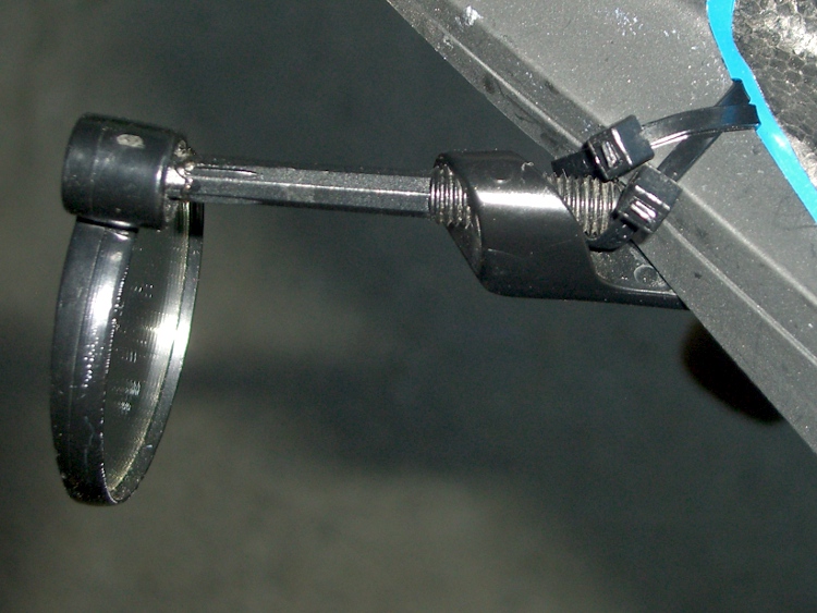
    Mirror on helmet again
    Mirror on helmet again
  • CPU Heatsink Fuzz Redux

    A friend donated an old Aptiva with an AMD K6 CPU to my collection. It’s too slow & power-hungry to be useful, so I harvested some useful bits and passed the corpse along to the recyclers.

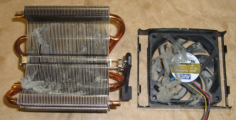
    As fate would have it, I have an upcoming project that needs a cooler, so I popped the fan off the top (it’s rotated a quarter-turn: those tabs lock over the edges of the heatsink) to see what’s inside…

    Fuzz in AMD K6 CPU Cooler
    Fuzz in AMD K6 CPU Cooler

    That accumulation was pretty much invisible from the outside, with most of the fuzz clotted around the periphery of the fan duct. The fan blows downward into the heatsink, which acted (as usual) as a good dust filter.

    A bit of vacuum cleaner work and it’ll be just fine.

    Memo to Self:

    1. The bottom of the heatsink is a 42×78 mm copper block with the heat pipes soldered into notches. Clearance from the block to the step below the widest part of the fins is 18 mm and the fins are 25 mm above the block surface.
    2. Fan = 12 @ 70 mA. Reasonably quiet.
    3. The small blue heat sensor (at about 8 o’clock in the picture) is upstream of the heatsink and, thus, measures ambient air . It’s essentially open-circuit at room temperature, but a diode test shows 1.4 V in either direction. That suggests it’s not a thermistor or thermocouple, but the CPU is old enough that it’s likely not a fancy IC, either. A puzzlement.
  • Arduino Connector & Hole Coordinates: Mega 1280 board

    The Arduino Mega uses the ATMega 1280 chip to get more memory and far more analog & digital & PWM I/O pins, but remains more-or-less header-pin-compatible with the older Duemilanove and Diecimila boards (notes on the header coordinates for those boards is there).

    Arduino Mega - ATmega1280 chip
    Arduino Mega – ATmega1280 chip

    Herewith, some useful coordinates for the Mega board in (X,Y) format using the default 0.001 grid: 1 unit = 0.001 inch (a.k.a 1 mil). Values are taken directly from the Eagle PCB layout.

    The board outline is bounded by (2100,4000) on the upper right, with (0,0) at the lower left by the power jack. It’s not rectangular, but a conversation with Mr Belt Sander could remove the tab sticking out to the right beyond JP1/JP2 if that were really important.

    The header names are not the same as on the old boards. Bolded values seem unusual.

    • PWMH 1×8 @ (1300,2000) ← X is not 1290 as before!
    • PWML 1×8 @ (2150,2000)
    • COMMUNICATION 1×8 @ (3050,2000)
    • JP1 2×8 @ (3750,1550)
    • JP2 2×8 @ (3750,750)
    • POWER 1×6 @ (1550,100)
    • ADCL 1×8 @ (2350,100)
    • ADCH 1×8 @ (3250,100)
    • ICSP 2×3 @ (2555,1100) ← +5 X offset
    • Reset switch @ (2920,1100) ← -30 X offset

    The PWMH header is 10 mils to the right of its position on the older boards, but still not on the same grid used by the other headers: it’s now offset by a nice, even 50 mils. This probably doesn’t matter for most headers, given the sloppy fit. If you have a finicky board setup, you’re in trouble.

    Here’s what the PWMH and PWML headers look like, measured against a Duemilanove board on the top. The offset is not due to perspective!

    Arduino Mega PWMH header offset
    Arduino Mega PWMH header offset

    The Mega board has four 0.125-inch diameter mounting holes (they use 125.984, which is a hard-metric 3.2 mm). The first one is at the same position as on the Duemilanove board.

    • (600,2000)
    • (600,100)
    • (3550,2000)
    • (3800,100)

    Three fiducials:

    • 1 @ (780,2000)
    • 2 @ (2319,1603) ← deliberately offset from the grid?
    • 3 @ (3800,100)

    Memo to Self: As always, verify these numbers before you start drilling!

  • Improved Tour Easy Chain Tensioner

    A discussion on that post reminded me of this old project: replacing the chain pulleys in the midships chain tensioner on my Tour Easy recumbent.

    The problem is that the original pulleys used steel bearings in a plastic race, for reasons that I cannot fathom. They last for a few thousand miles, then get very wobbly and noisy. The solution, as nearly as I can tell, is to replace them with pulleys using cartridge bearings.

    This is what one looks like after four years slung below my bike. Surprisingly, the bearings still feel just fine, even though they’re not really sealed against the weather.

    Tour Easy - Cartridge Bearing Chain Tensioner
    Tour Easy – Cartridge Bearing Chain Tensioner

    Gotcha: the OEM pulleys are not the same OD / number of teeth as pulleys found in rear derailleurs.

    Soooo, after a bit of Quality Shop Time, I had these…

    Tour Easy Replacement Idler Pulley
    Tour Easy Replacement Idler Pulley

    This is where you really want an additive machining process, as I turned most of a big slab of aluminum into swarf while extracting each pulley.

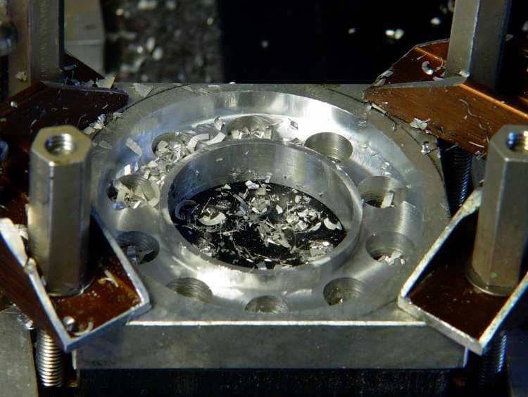
    The first step is to drill holes around the perimeter where the chain rollers will fit, plus drill out as much of the center bore as possible. Then mill down to the finished thickness across the roller holes and helix-mill the bore to size.

    Side 1
    Side 1

    Flip it over and mill the other side to the proper thickness.

    Run it through the bandsaw to chop off all the material beyond the outer diameter.

    Grab what’s left in the three-jaw chuck and mill around the perimeter to get a nice clean edge.

    Side 2
    Side 2

    And then it Just Works. I made another for Mary’s bike, but she said it was too noisy (which is why they used plastic rather than aluminum) and I swapped it for a Terracycle idler.

    This is from back in the Bad Old Days before EMC2’s version of G-Code supported loops. You don’t need to see that code, trust me on this.