-
CO₂ Laser Tube Current vs. Analog Control
Up to this point, the Ruida KT332N controller has set the laser power supply current from the
PWMterminal:
Ruida KT332 – PWM laser control wiring The blue and purple wires go off to the oscilloscope I’ve been using to measure how the controller and power supply behave.
The
L-ANterminal produces an equivalent analog signal: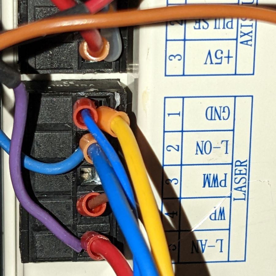
Ruida KT332 – analog laser control wiring The power supply accepts both analog and PWM signals on its
INterminal, so no rewiring was needed on that end: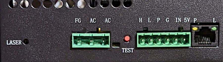
OMTech 60W HV power supply – terminals This test pattern came in handy again:

Gray bars The pattern has white bars on the left and right edges as markers. I invert the pattern in LightBurn so that white produced 100% PWM and black produced 0% PWM.
The
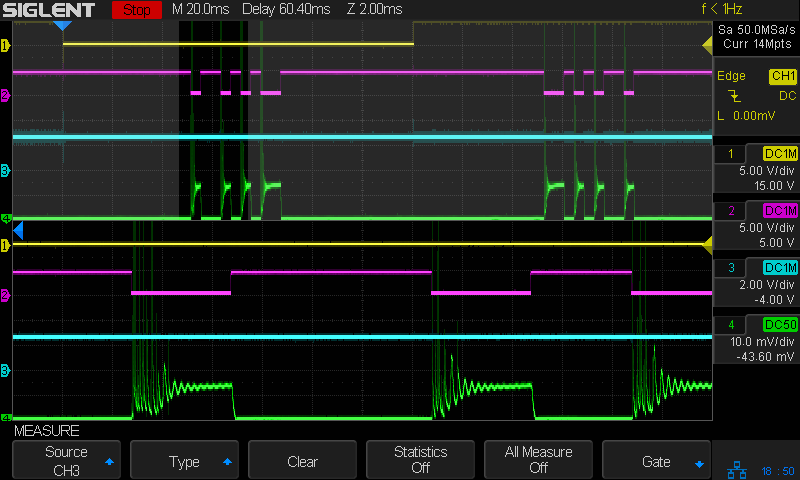
L-ANoutput produces 5 V for 100% power and 0 V for 0% power, with other power fractions spread out in between:
Tube Current – analog – gray bars – 10 ma-div The traces:
- 1 X axis
DIR, low = left-to-right (yellow) - 2
L-ONlaser enable, low active (magenta) - 3
L-ANanalog voltage (cyan) - 4 tube current – 10 mA/div (green)
Engraving that pattern in scrap acrylic looks like you’d expect:
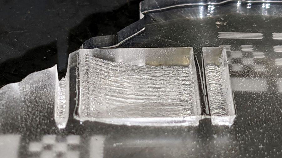
Analog mode acrylic engraving There’s little trace of the discrete intensity levels in the acrylic trench and the scan interval is a rather coarse 0.2 mm.
The analog-mode current looks remarkably like the PWM-mode current for the same test pattern:

Tube Current – grayscale bars – 100mm-s 10ma-div The PWM signal does not appear in that scope shot, because it runs at 20 kHz and is a blur at 20 ms/div.
It’s worth noting that the tube current has large startup spikes at low power levels in both PWM and analog control, so the spikes are generated internal to the power supply and have nothing to do with the PWM input signal.
Another test pattern using constant power:

Pulse Timing Pattern – 1 mm blocks At 10% power the analog output is about 0.5 V:

Tube Current – analog – 10pct 250mm-s – 10 ma-div At 50% power the analog output is a constant 2.5 V and the tube current settles at a constant 12-ish mA, about half of the power supply’s maximum 25 mA:
Tube Current – analog – 50pct 250mm-s – 10 ma-div Obviously, controlling the laser power to intermediate values using an analog signal does not involve switching the current between the supply’s minimum and maximum values: there are no PWM pulses involved to do the switching.
I suspect the analog output comes from the PWM signal run through an internal low-pass filter similar to the one in the power supply. Based on the PWM frequency measurements and squinting at the rise / fall times, the analog filter cutoff is probably around 1 kHz.
Other than bragging rights, I don’t see much advantage to using the analog signal in place of PWM.
- 1 X axis
-
Subscribe
Subscribed
Already have a WordPress.com account? Log in now.
