-
CO₂ Laser Tube Current: PWM Bandwidth
As with the analog bandwidth measurements, start with the same sine-bar bandwidth target:

Sine bars – 10 cycles Return the laser power supply’s IN terminal (and the purple wire to the oscilloscope) to the Ruida KT332N controller’s PWM output:

Ruida KT332 – PWM laser control wiring Engraving the pattern in grayscale mode at 254 dpi produces 0.1 mm pixels and makes each bar 1 mm wide:
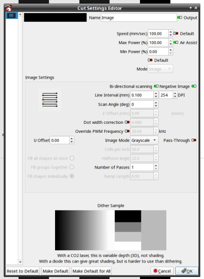
LightBurn – bandwidth test pattern setup Engraving at 50 mm/s = 50 Hz lets the laser current once again hit full scale:

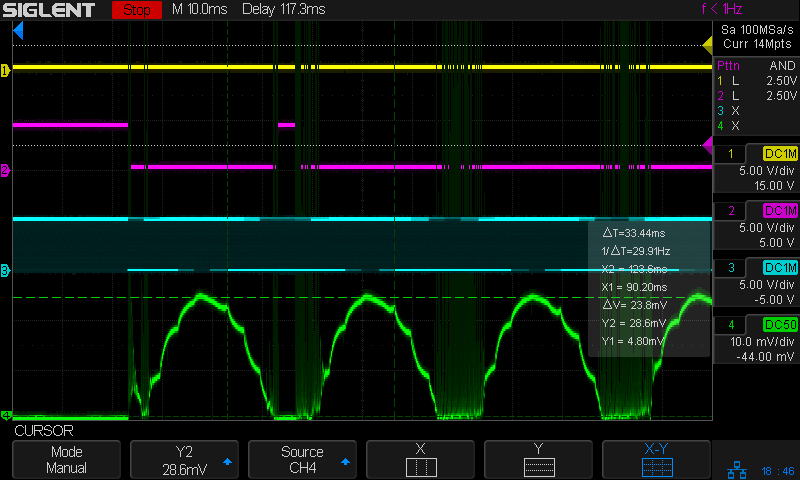
Tube Current – PWM bandwidth – 10 sine – 50mm-s – 10ma-div – 254dpi The traces:
- 1 X axis
DIR, low = left-to-right (yellow) - 2
L-ONlaser enable, low active (magenta) - 3
PWMdigital signal (cyan) - 4 tube current – 10 mA/div (green)
The
PWMsignal runs at 20 kHz and presents itself as a rather blurred trace, but you can see both the general tendency and the discrete steps between the vertical gray bars. As far as I can tell, the signal never reaches 0% or 100%, most likely to prevent the PWM filters from saturating in either condition.The tube current drops from 23.8 mA to 13.8 mA, just over the half-power level of 12 mA, at 200 Hz:

Tube Current – PWM bandwidth – 10 sine – 200mm-s – 10ma-div – 254dpi So the PWM bandwidth is a little over 200 Hz, slightly higher than the analog bandwidth of a little under 200 Hz.
All of the measurements as a slide show:
Tube Current – PWM bandwidth – 10 sine – 25mm-s – 10ma-div – 254dpi 
Tube Current – PWM bandwidth – 10 sine – 50mm-s – 10ma-div – 254dpi 
Tube Current – PWM bandwidth – 10 sine – 100mm-s – 10ma-div – 254dpi 
Tube Current – PWM bandwidth – 10 sine – 200mm-s – 10ma-div – 254dpi 
Tube Current – PWM bandwidth – 10 sine – 300mm-s – 10ma-div – 254dpi 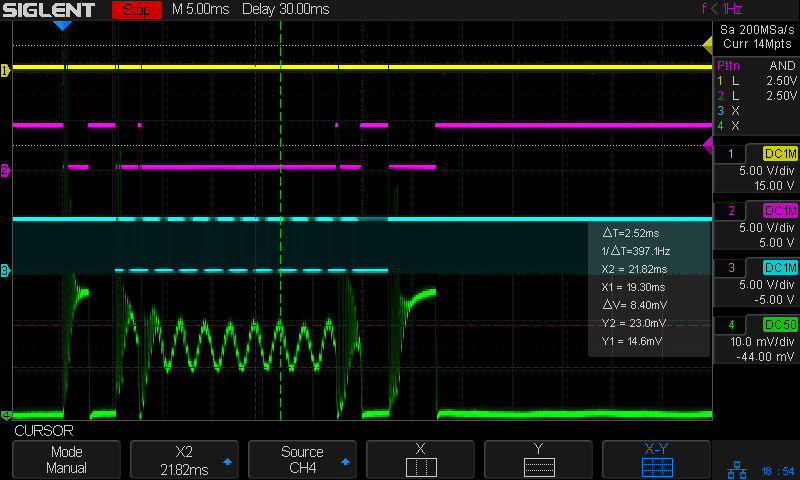
Tube Current – PWM bandwidth – 10 sine – 400mm-s – 10ma-div – 254dpi 
Tube Current – PWM bandwidth – 10 sine – 500mm-s – 10ma-div – 254dpi
Now, with all the measurements in hand, maybe I can reach some sort of conclusion.
- 1 X axis
-
Subscribe
Subscribed
Already have a WordPress.com account? Log in now.
