-
Harbor Freight Bar Clamp: New Handle
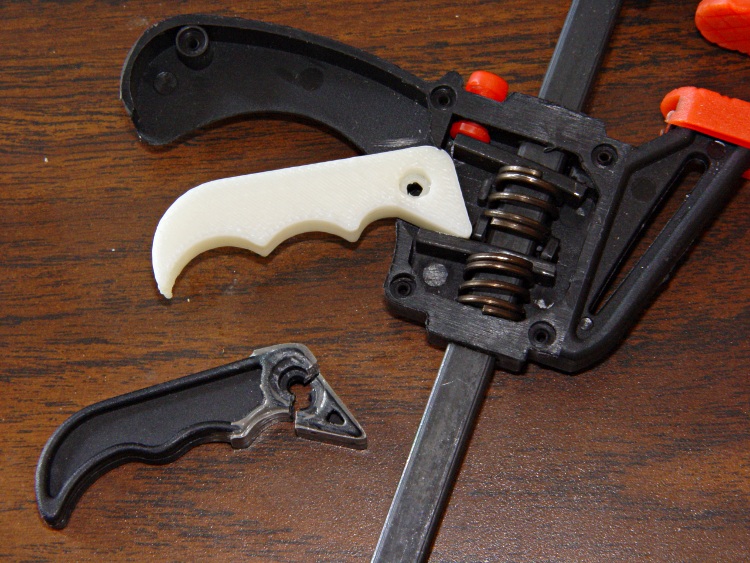
Conjuring up a replacement handle for that broken Harbor Freight bar clamp turned out to be easier than I expected:
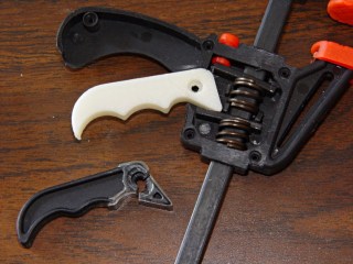
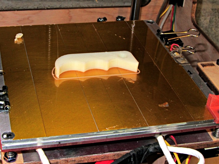
HF bar clamp handle – installed The thing omits the original’s fancy edge rounding, because I just hit the finger grips with a rat-tail file after it cooled:
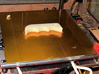
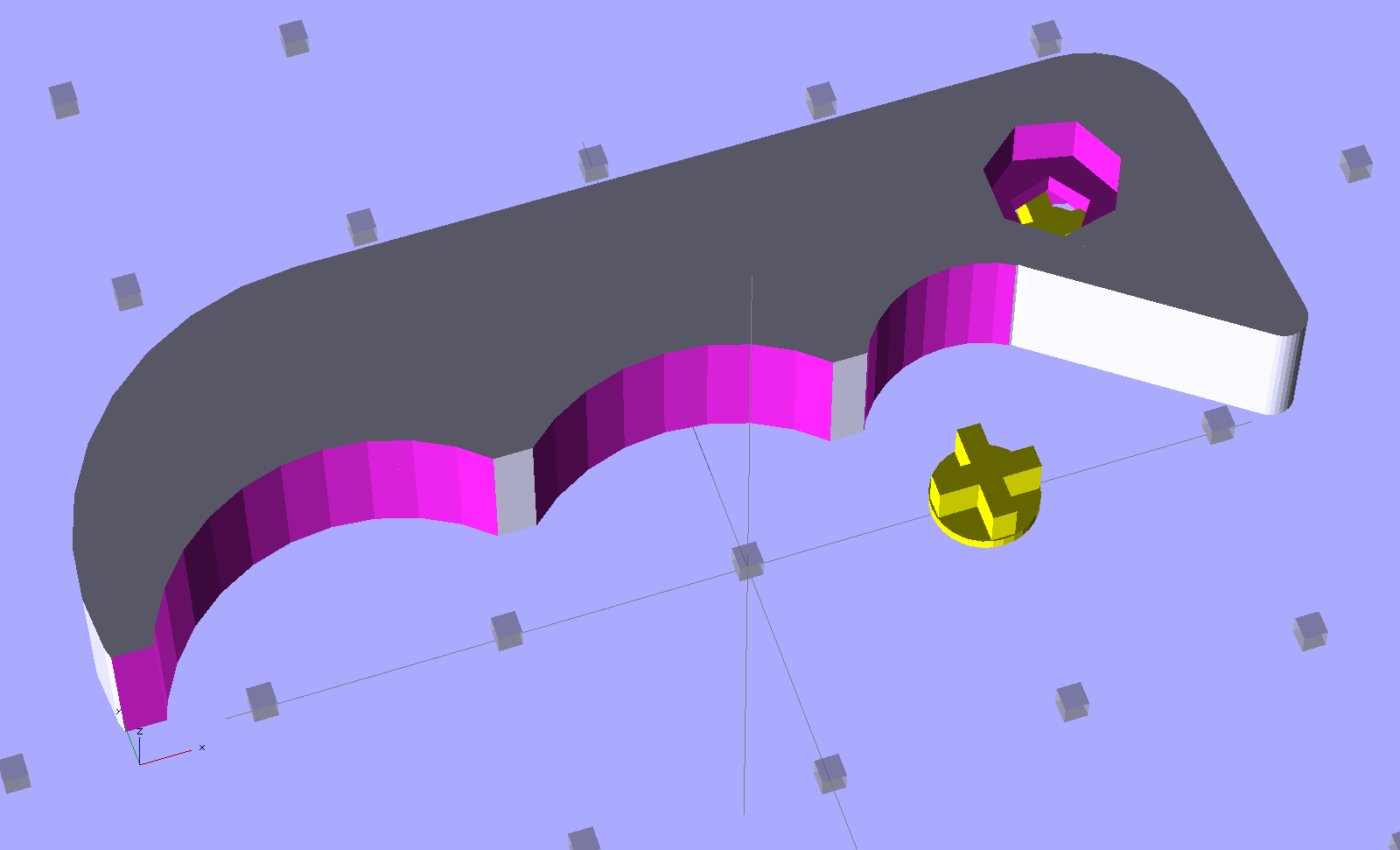
HF bar clamp handle – build platform The solid model uses OpenSCAD’s hull() operation for the beak and straight side of the handle, with a handful of circles chopping out the recesses. The rightmost arc lies tangent to the near side of the beak, so as to join without a stress-raiser bump:
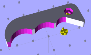
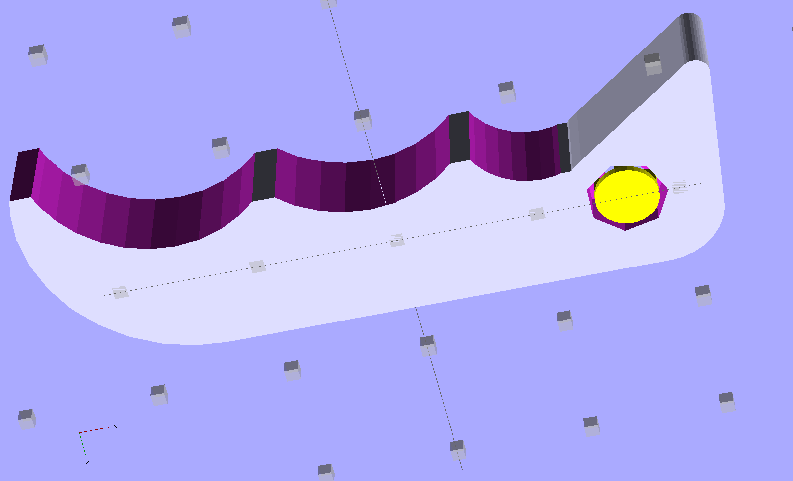
HF Bar Clamp – support – solid model The little yellow doodad is (a duplicate of) the support structure inside the pivot hole that prevents the middle section from drooping. It’s easier to see from the bottom:
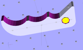
HF Bar Clamp – solid model – bottom Removing the plug required nothing more than a fat pin punch and a whack from a brass hammer, with the plug centered over a hole in a random chunk of aluminum (with many other holes):
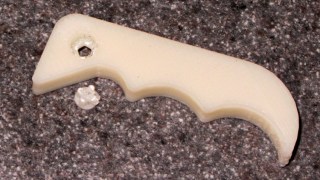
HF bar clamp handle – support plug removed Much to my delight, the holes & pivot recesses came out exactly the right size on the first version, with HoleWindage = 0.2. What’s new & different: that the first layer height has stabilized at 0.25 mm and the first few layers don’t get squished.
I built three more handles in one setup, just to have some show-n-tell objects, with one prepped and on hot standby should the other Harbor Freight handle break. If these handles break, something aluminum on the Sherline will be in order.
Now that clamp can go back into the collection. Puzzle: which one isn’t like the other ones?
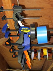
Too many bar clamps I should’a used Safety Orange filament, eh?
[Update: xylitol designed a much better looking version that should be a drop-in replacement. Perhaps you can print it standing on edge (or end) to eliminate the support structures?]
The OpenSCAD source code:
// Handle for Harbor Freight bar clamp
// Ed Nisley KE4ZNU - Jan 2012

Layout = "Show";                // Build Show

Support = true;
SupportColor = "Yellow";

//- Extrusion parameters must match reality!
//  Print with +1 shells and 3 solid layers
//  Use infill solidity = 0.5 or more...

ThreadThick = 0.25;
ThreadWidth = 2.0 * ThreadThick;

HoleWindage = 0.2;

Protrusion = 0.1;           // make holes end cleanly

CircleSides = 4*8;
$fn = CircleSides;

//-------
// Handle dimensions

OALength = 49;
OAThickness = 6.0;

BodyWidth = 12;

BeakRadius = 12;                            // hole to tip
BeakEndRadius = 1.0;                        // roundness of tip
BeakIncludedAngle = 40;
BeakAngle = 55;
BeakAdder = [2.0,1.0];                      // additional meat on outer and upper sides

BeakHalfWidth = IntegerMultiple(BeakRadius*sin(BeakIncludedAngle/2),ThreadWidth);

PivotXY = BeakRadius*[cos(BeakAngle),sin(BeakAngle)]; // pivot hole offset from beak tip

PivotShaftDia = 2.6;
PivotRecessDia = 5.0;
PivotRecessDepth = 2.5;

NumScallops = 3;
ScallopRadius = [5,9,9];        // first scallop must be tangent to beak!
ScallopX = [-((ScallopRadius[0] + BeakHalfWidth)*cos(90 - (BeakAngle - BeakIncludedAngle/2))),
            -17.5,-31.5];
ScallopY = [-((ScallopRadius[0] + BeakHalfWidth)*sin(90 - (BeakAngle - BeakIncludedAngle/2))),
            -12,-12];

echo(str("Scallops R=",ScallopRadius," X=",ScallopX," Y=",ScallopY));

TailOuterRadius = 12;
TailInnerRadius = 22;

//-------

function IntegerMultiple(Size,Unit) = Unit * ceil(Size / Unit);

module PolyCyl(Dia,Height,ForceSides=0) {           // based on nophead's polyholes

  Sides = (ForceSides != 0) ? ForceSides : (ceil(Dia) + 2);

  FixDia = Dia / cos(180/Sides);

  cylinder(r=(FixDia + HoleWindage)/2,h=Height,$fn=Sides);
}

module ShowPegGrid(Space = 10.0,Size = 1.0) {

  Range = floor(50 / Space);

    for (x=[-Range:Range])
      for (y=[-Range:Range])
        translate([x*Space,y*Space,Size/2])
          %cube(Size,center=true);

}

//-------
// Bits and pieces

module Pivot() {

  translate([0,0,-Protrusion])
    PolyCyl(PivotShaftDia,(OAThickness + 2*Protrusion));

  translate([0,0,(OAThickness - PivotRecessDepth)])
    PolyCyl(PivotRecessDia,(PivotRecessDepth + Protrusion));

  translate([0,0,-Protrusion])
    PolyCyl(PivotRecessDia,(PivotRecessDepth + Protrusion));

}

module HandleBlock() {

  hull() {                            // beak
    cylinder(r=BeakHalfWidth,h=OAThickness);
    translate(BeakAdder)
      cylinder(r=BeakHalfWidth,h=OAThickness);
    translate([(PivotXY[0] - BeakEndRadius*cos(BeakAngle)),
              -(PivotXY[1] - BeakEndRadius*sin(BeakAngle))])
      cylinder(r=BeakEndRadius,h=OAThickness);
  }

  hull() {                            // straight body edge
    translate(BeakAdder)
      cylinder(r=BeakHalfWidth,h=OAThickness);
    translate([-(OALength - PivotXY[0] - TailOuterRadius),BeakAdder[1]])
      cylinder(r=BeakHalfWidth,h=OAThickness);
  }

  translate([ScallopX[0],0,0])        // scalloped edge tips
    rotate(180)
      cube([(OALength - PivotXY[0] + ScallopX[0] - TailOuterRadius),
            (BodyWidth/2 - ThreadWidth),      // small Finagle constant = flat tips
            OAThickness],center=false);

  translate([-(OALength - PivotXY[0] - TailOuterRadius),        // tail
            (BeakHalfWidth + BeakAdder[1] - TailOuterRadius)])
    rotate(180)
      intersection() {
        cylinder(r=TailOuterRadius,h=OAThickness);
        translate([0,-TailOuterRadius])
          cube([TailOuterRadius,2*TailOuterRadius,OAThickness]);
      }

}

module SupportPlug() {

  color(SupportColor)
  union() {
    cylinder(r=IntegerMultiple((PivotRecessDia - ThreadWidth),ThreadWidth)/2,
              h=2*ThreadThick);
    for (Index=[0,1])
      rotate(Index*90)
        translate([0,0,(PivotRecessDepth - ThreadThick)/2])
          cube([(PivotRecessDia - ThreadWidth - 2*Protrusion),
                2*ThreadWidth,(PivotRecessDepth - ThreadThick)],
              center=true);
  }
}

//------

module Handle() {

    difference() {
      HandleBlock();

      translate([-(OALength - PivotXY[0] - TailOuterRadius),    // trim tail tip
                -(PivotXY[1] - ThreadWidth),
                -Protrusion])
        rotate(180)
          cube([TailOuterRadius,TailOuterRadius,(OAThickness + 2*Protrusion)]);

      for (Index=[0:NumScallops-1]) {
        translate([ScallopX[Index],ScallopY[Index],-Protrusion])
          cylinder(r=ScallopRadius[Index],h=(OAThickness + 2*Protrusion));
      }

      Pivot();
    }

    if (Support)                    // choose support to suit printing orientation
      SupportPlug();
}

//-------

ShowPegGrid();

if (Layout == "Show") {
  translate([OALength/3,10,0])
    Handle();
  translate([10,0,0])
    SupportPlug();
}

if (Layout == "Build")
  translate([OALength/3,0,0])
    Handle();
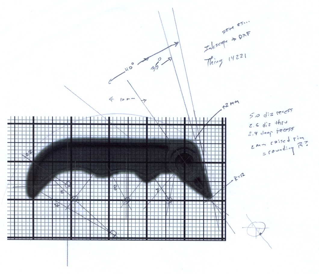
The original doodles, which I started by scanning an unbroken handle and overlaying a grid, then scaling the grid so the end-to-end measurement worked out to the proper number of millimeters:
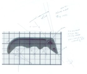
Handle dimension doodles


-
Subscribe
Subscribed
Already have a WordPress.com account? Log in now.
 The Smell of Molten Projects in the Morning