-
Automated Cookie Cutters: Putting It All Together
With that musing, image processing, and data reformatting in hand, this now seems to work pretty well…
This is
MakeCutter.sh, the Bash file that controls the overall process:#!/bin/bash DotsPerMM=3 MapHeight=5 ImageName=${1%%.*} rm ${ImageName}_* ${ImageName}.stl echo Normalize and prepare grayscale image... convert $1 -trim -type Grayscale -depth 8 -auto-level -flip -negate -flop ${ImageName}_prep.png echo Create PGM files... convert ${ImageName}_prep.png -compress none ${ImageName}_map.pgm convert ${ImageName}_prep.png -white-threshold 1 -compress none ${ImageName}_plate.pgm echo Create height map data files... ImageX=`identify -format '%[fx:w]' ${ImageName}_map.pgm` ImageY=`identify -format '%[fx:h]' ${ImageName}_map.pgm` cat ${ImageName}_map.pgm | tr -s ' \012' '\012' | tail -n +5 | column -x -c $((8*$ImageX)) > {ImageName}_map.dat cat ${ImageName}_plate.pgm | tr -s ' \012' '\012' | tail -n +5 | column -x -c $((8*$ImageX)) > ${ImageName}_plate.dat echo Create height map STL files... time openscad -D DotsPerMM=$DotsPerMM -D Height=$MapHeight -D FileName=\"${ImageName}_map.dat\" -o ${ImageName}_map.stl MakeSurface.scad time openscad -D DotsPerMM=$DotsPerMM -D Height=255 -D FileName=\"${ImageName}_plate.dat\" -o ${ImageName}_plate.stl MakeSurface.scad echo Create cookie press and cutter... time openscad -D fnPress=\"${ImageName}_map.stl\" -D fnPlate=\"${ImageName}_plate.stl\" -D ImageX=$ImageX -D ImageY=$ImageY -o ${ImageName}.stl Cookie\ Cutter.scadHand it an image file name and it just does the rest:
./MakeCutter.sh jellyfish-high.png
I assume you’ll pick a workable dots/mm resolution and suchlike for your setup, so they’re hardcoded into the script. You could add them to the command line if you like.
Starting from the same
jellyfish.svgfile as before, I came up with a slightly differentjellyfish-high.pnggrayscale height map image with more dots (246×260 dots at 3 dot/mm = 82×87 mm). The original 160×169 file required about half an hour to render and, as you’d expect, increasing the number of dots by 1.5 (nearly √2) doubled the time to just over an hour:
Manually tweaked jellyfish-high.png The first
convertstep turns that into the basic height mapjellyfish_prep.pngfile:
jellyfish-high_prep.png The next two
convertsteps produce two ASCIIPGMfiles:jellyfish-high_map.pgmjellyfish-high_plate.pgm
The
_mapfile has the grayscale height map data, which is identical to the preparedPNGimage:
jellyfish-high_map The
_platefile defines the outline of the cookie cutter with a completely white interior, which is why the original cookie height map image can’t contain any pure white areas inside the outline (they’d become black here and produce islands). It seems the OpenSCADminkowski()function runs significantly faster when it doesn’t process a whole bunch of surface detail; all we care about is the outline, so that’s all it gets:
jellyfish-high_plate I originally composited the height maps on a known-size platen and worked with those dimensions, but it’s easier to just extract the actual image dimensions and feed them into the code as needed. As with all ImageMagick programs,
identifyhas a myriad options.Those two lines of Bash gibberish reformat the ASCII
PGMfiles into the ASCIIDATarrays required by OpenSCAD’ssurface()function.The
MakeSurface.scadscript eats aDATheight map file and spits out a correspondingSTLfile. TheHeightparameter defines the overall Z-axis size of the slab; the maximum 255 corresponds to pure white in the image file:// Generate object from image height map // Ed Nisley - KE4ZNU // October 2012 // This leaves the rectangular slab below Z=0 over the full image area // ... reduced in thickness by the Height/255 ratio FileName = "noname.dat"; // override with -D FileName="whatever.dat" Height = 255; // overrride with -D Height=number DotsPerMM = 2; // overrride with -D DotsPerMM=number ScaleXYZ = [1/DotsPerMM,1/DotsPerMM,Height/255]; echo("File: ",FileName); echo("Height: ",Height); echo("Dots/mm: ",DotsPerMM); echo("Scale: ",ScaleXYZ); module ShowPegGrid(Space = 10.0,Size = 1.0) { Range = floor(50 / Space); for (x=[-Range:Range]) for (y=[-Range:Range]) translate([x*Space,y*Space,Size/2]) %cube(Size,center=true); } //- Build it ShowPegGrid(); scale(ScaleXYZ) surface(FileName,center=true,convexity=10);The grid defining the build platform doesn’t show up in the output file; it’s there just for manual fiddling inside the GUI. When run from the command line, OpenSCAD simply creates the output file.
The
_map.stlfile has the height map data that will form the cookie press: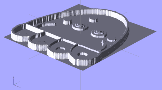
jellyfish-high_map – Model The
_plate.stlfile is basically a digital bar cookie that will define the cutter: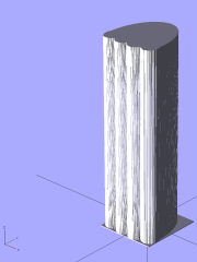
jellyfish-high_plate – Model It’s possible to produce the cutter in one shot, starting from the
DATfiles, but having the twoSTLfiles makes it (barely) feasible to experiment interactively within the OpenSCAD GUI.This OpenSCAD program produces the cutter and press:
// Cookie cutter from grayscale height map using Minkowski sum
// Ed Nisley KE4ZNU - November 2012

//-----------------
// Cookie cutter files

BuildPress = true;
BuildCutter = true;

fnPress = "nofile.stl";					// override with -D 'fnPress="whatever.stl"'
fnPlate = "nofile.stl";					// override with -D 'fnPlate="whatever.stl"'

ImageX = 10;						// overrride with -D ImageX=whatever
ImageY = 10;

MaxConvexity = 5;					// used for F5 previews in OpenSCAD GUI

echo("Press File: ",fnPress);
echo("Plate File: ",fnPlate);
echo("Image X: ",ImageX," Y: ",ImageY);

//- Extrusion parameters - must match reality!

ThreadThick = 0.25;
ThreadWidth = 2.0 * ThreadThick;

//- Cookie cutter parameters

TipHeight = IntegerMultiple(8,ThreadThick);		// cutting edge
TipWidth = 4*ThreadWidth;

WallHeight = IntegerMultiple(7,ThreadThick);		// center section
WallWidth = 8*ThreadWidth;

LipHeight = IntegerMultiple(2.0,ThreadThick);		// cutter handle
LipWidth = IntegerMultiple(8.0,ThreadWidth);

CutterGap = IntegerMultiple(2.0,ThreadWidth);		// gap between cutter and press

PlateThick = IntegerMultiple(3.0,ThreadThick);		// solid plate under press relief

//- Build platform

PlatenX = 100;						// build platform size
PlatenY = 120;
PlatenZ = 120;						// max height for any object
PlatenFuzz = 2;

MaxSize = max(PlatenX,PlatenY);				// larger than any possible dimension ...

ZFuzz = 0.20;						// height of numeric junk left by grayscale conversion
ZCut = 1.20;						// thickness of block below Z=0

//- Useful info

function IntegerMultiple(Size,Unit) = Unit * ceil(Size / Unit);

Protrusion = 0.1;					// make holes and unions work correctly

//-----------------
// Import height map STL, convert to cookie press image

module PressSurface() {

	translate([0,0,-ZFuzz])
		difference() {
			import(fnPress,convexity=MaxConvexity);
			translate([-(ImageX + PlatenFuzz)/2,-(ImageY + PlatenFuzz)/2,-ZCut])
				cube([(ImageX + PlatenFuzz),(ImageY + PlatenFuzz),ZCut+ZFuzz],center=false);
		}
}

//-----------------
// Import plate STL, slice off a slab to define outline

module Slab(Thick=1.0) {
	intersection() {
		translate([0,0,Thick/2])
			cube([(PlatenX+PlatenFuzz),(PlatenY+PlatenFuzz),Thick],center=true);
		translate([0,0,-1])
			import(fnPlate,convexity=MaxConvexity);
	}
}

//- Put peg grid on build surface

module ShowPegGrid(Space = 10.0,Size = 1.0) {

  Range = floor(50 / Space);

	for (x=[-Range:Range])
	  for (y=[-Range:Range])
		translate([x*Space,y*Space,Size/2])
		  %cube(Size,center=true);

}

//- Build it

ShowPegGrid();

if (BuildPress) {
	echo("Building press");
	union() {
		minkowski() {					// fingernail ridge around press
			Slab(LipHeight - 1);			//  ... same thickness as cutter lip
			cylinder(r=CutterGap/2,h=1);
		}
		translate([0,0,(LipHeight - Protrusion)])	// solid plate under press
			Slab(PlateThick - LipHeight + Protrusion);
		translate([0,0,PlateThick])			// cookie press height map
			intersection() {
				import(fnPress,convexity=MaxConvexity);
				translate([0,0,-Protrusion])
					Slab(PlatenZ + Protrusion);
			}

	}
}

if (BuildCutter) {
	echo("Building cutter");
	difference() {
		union() {					// stack cutter layers
			translate([0,0,(WallHeight + LipHeight - 1)])
				minkowski() {
					Slab(TipHeight - 1);
					cylinder(r=(TipWidth + CutterGap),h=1);
				}
			translate([0,0,LipHeight - 1])
				minkowski() {
					Slab(WallHeight - 1);
					cylinder(r=(WallWidth + CutterGap),h=1);
				}
			minkowski() {
				Slab(LipHeight - 1);
				cylinder(r=(LipWidth + CutterGap),h=1);
			}
		}
		minkowski() {					// punch out opening for cookie press
			translate([0,0,-2])
				Slab(PlatenZ);
			cylinder(r=CutterGap,h=1);
		}
	}
}
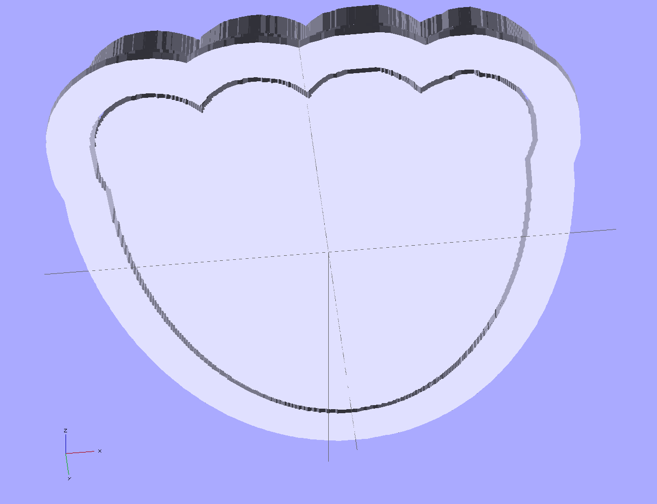
The top view shows the height map press nested inside the cutter blade, but it’s not obvious they’re two separate pieces:
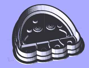
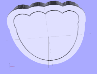
jellyfish-high – Cutter and Press – top view The bottom view shows the 1 mm gap between the two objects:
jellyfish-high – Cutter and Press – bottom view Now, to print the thing [Update: like that] so I can make some cookies…
Further musings:
- Printing separately would allow a tighter fit between the press and the cutter: an exact fit won’t work, but 2 mm may be too much.
- A knob glued on the flat surface of the press would be nice; the fingernail ridge may get annoying.
- PLA seems more socially acceptable than ABS for foodie projects. Frankly, I doubt that it matters, at least in this application.
- A bigger build platform would be nice…


-
Subscribe
Subscribed
Have a WordPress.com account? Log in now.

