-
Handi-Quilter HQ Sixteen: Anchor Block
Although I devoted considerable attention to leveling & shimming the table under Mary’s HQ Sixteen, the machine rolls on ball bearing wheels atop (relatively) smooth plastic tracks. Parked at a few spots along the dozen feet of table, the machine will slowly and quietly roll away. This calls for some sort of parking brake, but until inspiration strikes, a simple anchor will suffice:
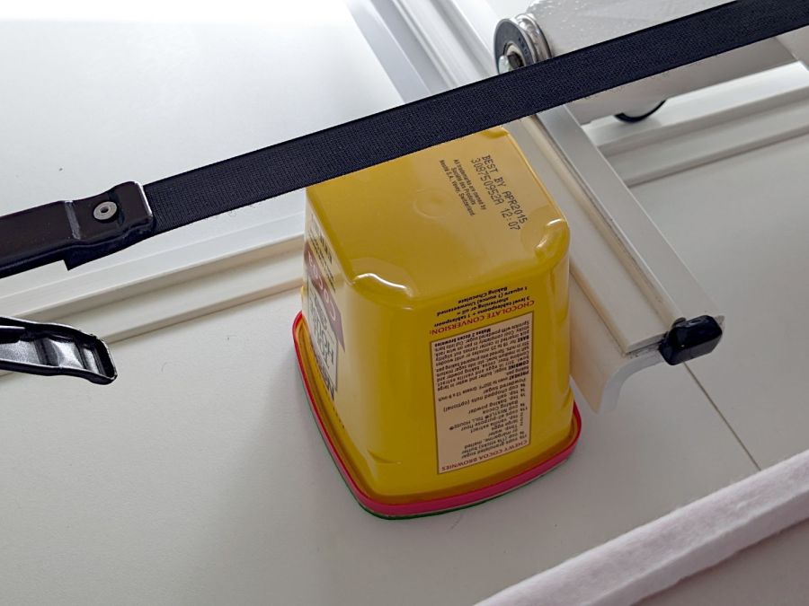
HQ Sixteen – anchor It’s a cocoa container chosen from (one of) my Boxes o’ Containers, with a husky chunk of steel atop some very sticky double-sided foam tape inside the red lid.
You can see one of the ball bearing wheel just above the strap applying tension to the practice quilt out of view on the left. The thing that looks like a wheel just under the strap is an encoder for the stitch regulator that we haven’t connected yet.
To prevent the machine from simply bulldozing the container along with it, the lid sits on a sheet of EVA craft foam stuck to a sheet of rigid foam board (with adhesive on both sides).
Scan the lid:
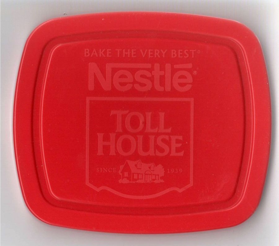
Container lid scan Select all the red pixels, do a little cleanup, turn it into a binary mask:

Container lid mask Import it into LightBurn, trace the perimeter, do some curve optimization / smoothing, duplicate the outline, set one to cut EVA foam and the other to cut adhesive board, and Fire The Laser.
Elapsed time: about fifteen minutes from realizing what was needed to plunking the anchor in place.
I briefly considered a full-frontal laser-cut finger-jointed box for the weight, but … Mary’s not a big fan of that campfire smell, particularly in a room dedicated to the Fiber Arts.
-
Subscribe
Subscribed
Already have a WordPress.com account? Log in now.
