-
Sewing Machine Lights: LED Strip Mount Solid Models
Mary’s Sears Kenmore Model 158 sewing machine arm has a flat rear surface and a plastic plate on the front, so double-sided adhesive foam tape can hold a straight mount in place; we rejected putting strips under the arm to avoid snagging on the quilts as they pass by. So, with LEDs in hand, these are the mounts…
LED strip lights must have strain relief for their wires, as our Larval Engineer discovered the hard way on her longboard ground lighting project, and I wanted nice endcaps to avoid snagging on the fabric, so the general idea was a quarter-round rod with smooth endcaps and a hole to secure the wire. Some experiments showed that the acrylic (?) LED encapsulation directed the light downward, thus eliminating the need for a shade.
So, something like this will do for a first pass:
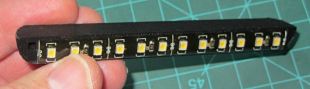
LED Strip Light Mount – bottom view The overall dimensions for the LED mounts:
- Length: N x 25 mm, plus endcap radii
- Front-to-back width: 10 mm to allow for strip variation and 1 mm protection
- Top-to-bottom height: 12 mm to fit double-sided foam sticky squares
- Wire channels: 3 mm diameter or square cross-section
If there’s not enough light, I think a double-wide mount with two parallel LED strips would work.
After a bit of screwing around with additive endcaps that produced catastrophically non-manifold solid models, I figured out the proper subtractive way to build the mounts: the endcaps actually define the overall shape of the mount.
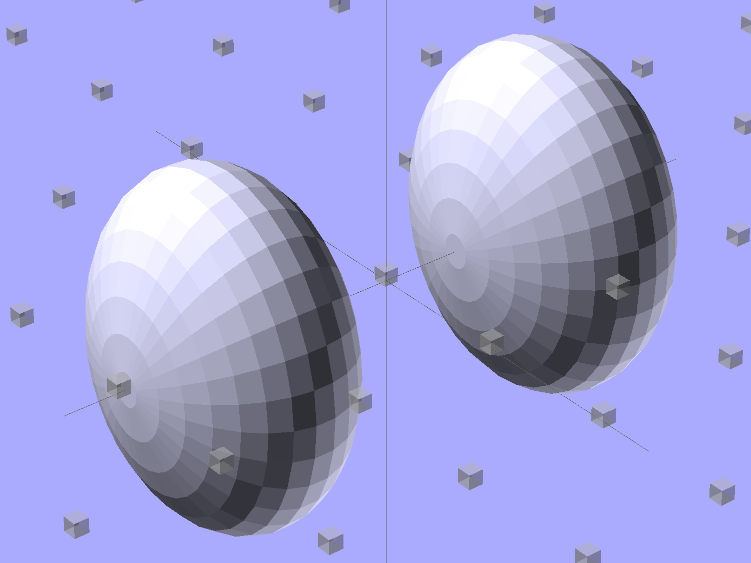
Start by placing a pair of spheroids, with radii matching the strip dimensions, so that their outer poles match the desired overall length:
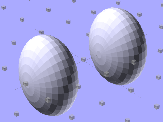
Strip Light Mount – end cap spheroids – whole The north/south poles must face outward, so that the equal-angle facets along the equators match up with what will become the mount body: rotate the spheroids 90° around the Y axis. The centers lie at the ends of the LED segments; the model shown here has a single 25 mm segment.
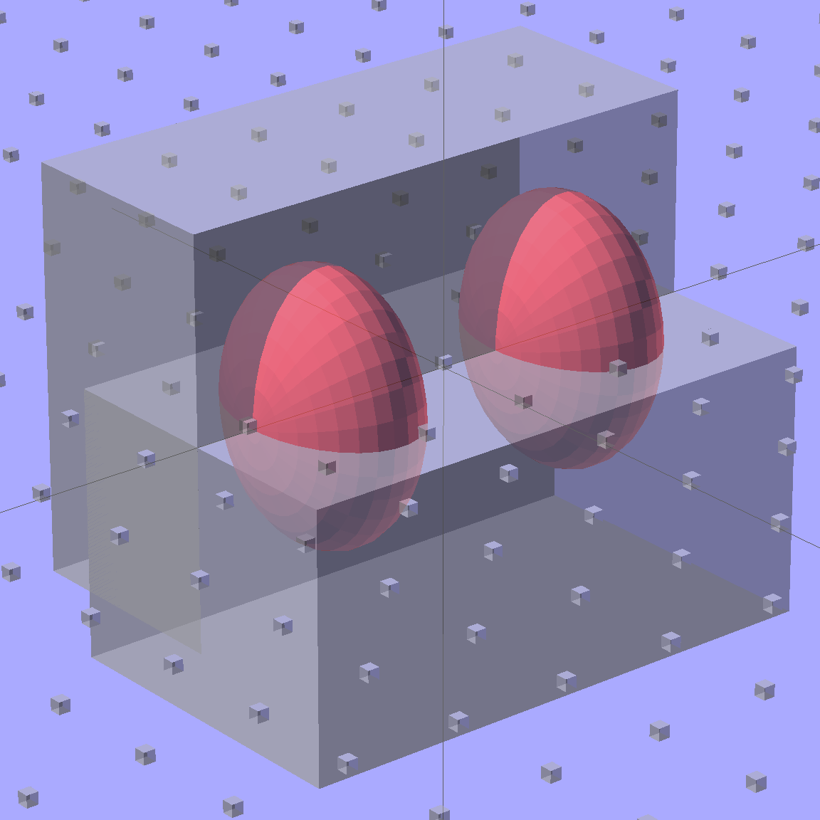
Then hack off three quadrants:
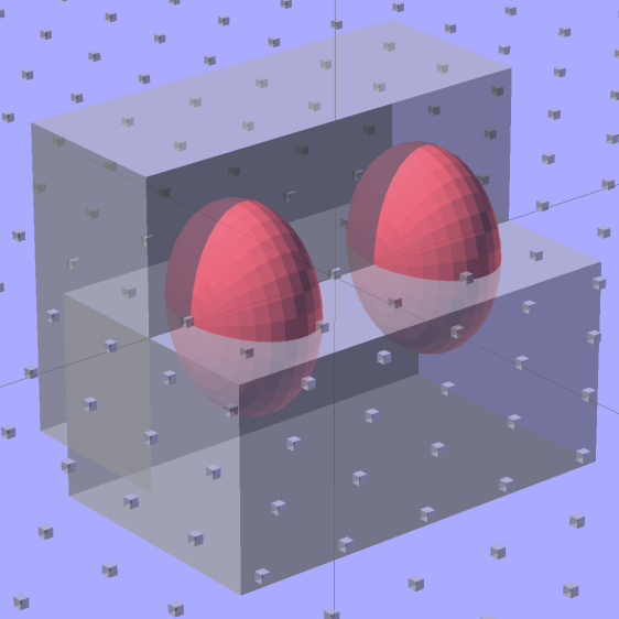
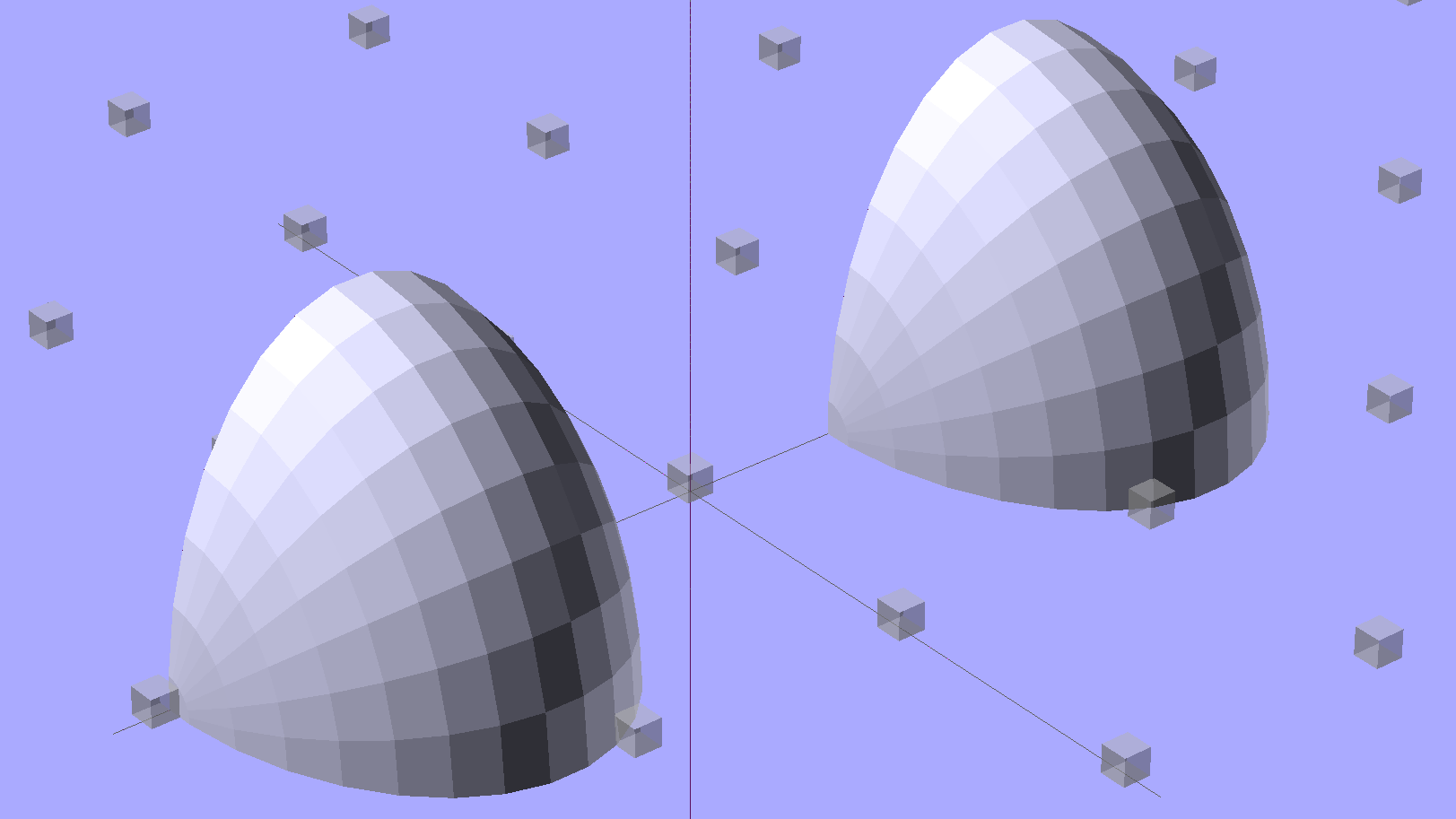
Strip Light Mount – end cap spheroids That leaves two orange-segment shapes that define the endcaps:
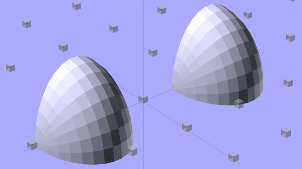
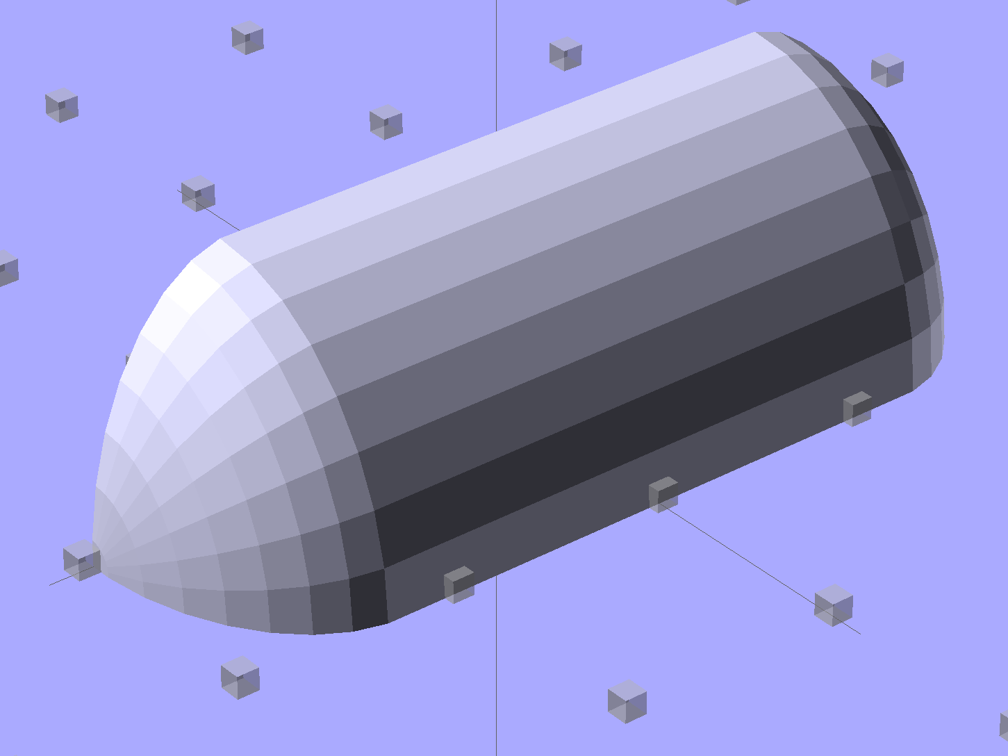
Strip Light Mount – end caps – shaped Here’s the key step that took me far too long to figure out. Shrinkwrapping the endcaps with the
hull()function finesses the problem of matching the body facets to the endcap facets: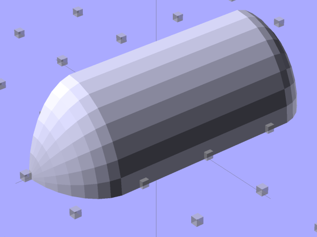
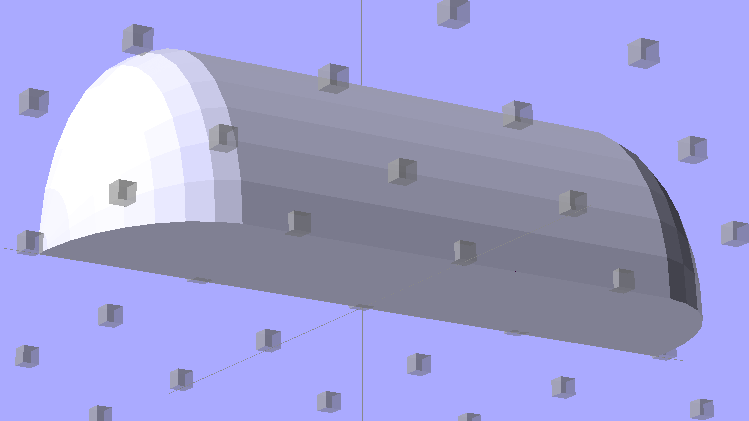
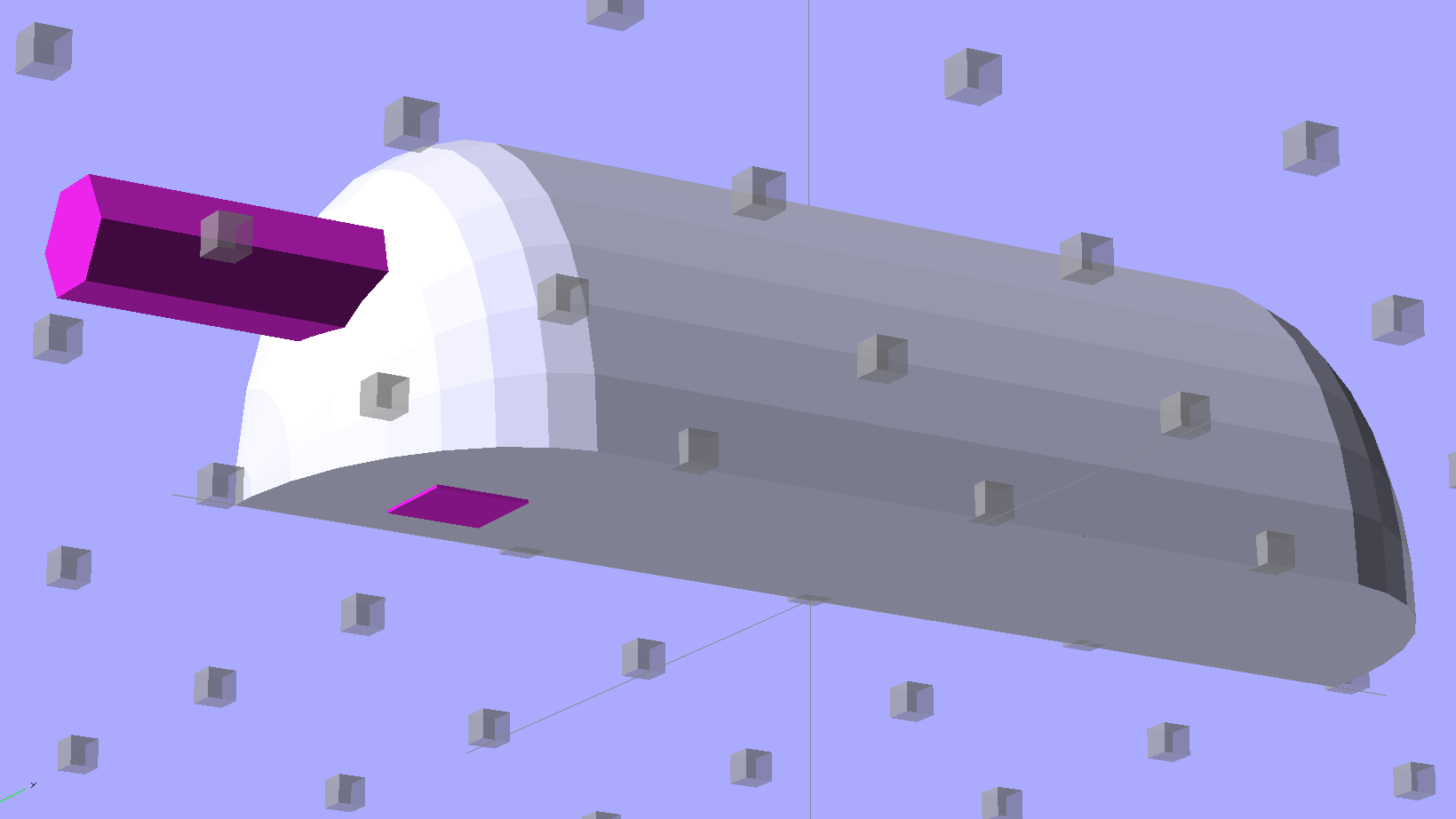
Strip Light Mount – end caps – hull Model the wire channels as positive volumes that will be subtracted from the mount. The
Channelslayout shows both channels separated by a short distance: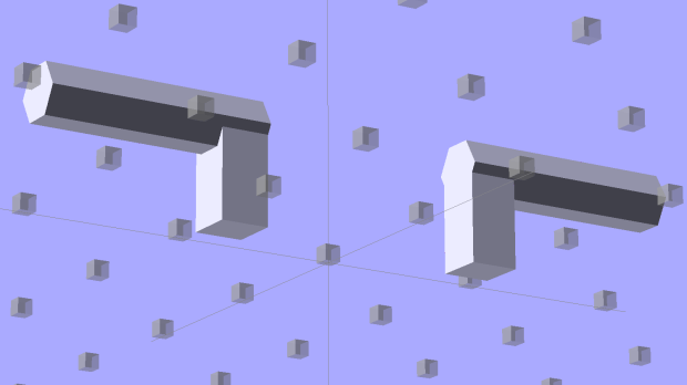
Strip Light Mount – positive wire channels The horizontal hexagons started as squares, but that looked hideous on the rounded endcaps.
Seen from the bottom, the mount starts like this:
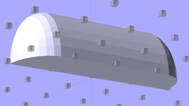
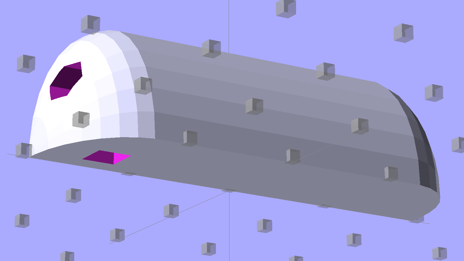
Strip Light Mount – no wiring channels Position and subtract a wire channel:
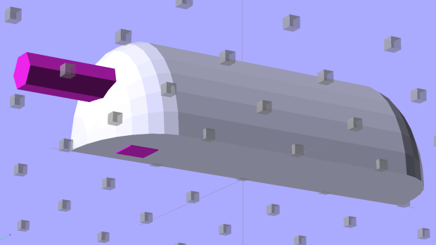
Strip Light Mount – visible wire channel Which leaves the final solid model as a single, manifold object:
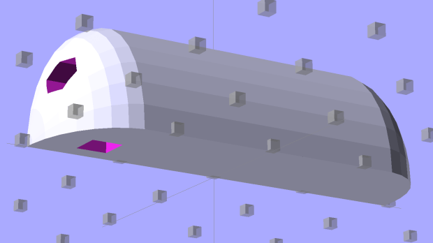
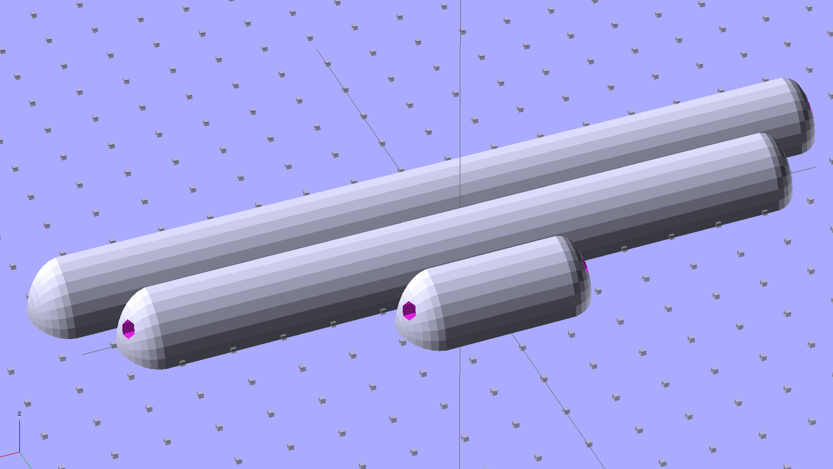
Strip Light Mount – complete The module generating the mount takes three parameters: the number of LED segments and two string variables that determine whether to punch a channel in each endcap. Instantiate the module three times with suitable parameters to get a trio of LED mounts, all laid out for 3D printing:
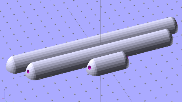
Strip Light Mount – build layout They built just exactly like those models would suggest; the M2 produces dependable results.
The OpenSCAD source code:
// LED Strip Lighting Brackets for Kenmore Model 158 Sewing Machine
// Ed Nisley - KE4ZNU - February 2014

Layout = "Strip";			// Build Show Channels Strip

//- Extrusion parameters must match reality!
//  Print with 2 shells and 3 solid layers

ThreadThick = 0.20;
ThreadWidth = 0.40;

HoleWindage = 0.2;			// extra clearance

Protrusion = 0.1;			// make holes end cleanly

AlignPinOD = 1.70;			// assembly alignment pins: filament dia

inch = 25.4;

function IntegerMultiple(Size,Unit) = Unit * ceil(Size / Unit);

//----------------------
// Dimensions

Segment = [25.0,10.0,3.0];		//  size of each LED segment

WireChannel = 3.0;				// wire routing channel

StripHeight = 12.0;				// sticky tape width
StripSides = 8*4;

DefaultLayout = [1,"Wire","NoWire"];

EndCap = [(2*WireChannel + 1.0),Segment[1],StripHeight];	// radii of end cap spheroid
EndCapSides = StripSides;

CapSpace = 2.0;						// build spacing for endcaps
BuildSpace = 1.5*Segment[1];		// spacing between objects on platform

//----------------------
// Useful routines

module PolyCyl(Dia,Height,ForceSides=0) {			// based on nophead's polyholes

  Sides = (ForceSides != 0) ? ForceSides : (ceil(Dia) + 2);

  FixDia = Dia / cos(180/Sides);

  cylinder(r=(FixDia + HoleWindage)/2,
           h=Height,
           $fn=Sides);
}

module ShowPegGrid(Space = 10.0,Size = 1.0) {

  RangeX = floor(100 / Space);
  RangeY = floor(125 / Space);

	for (x=[-RangeX:RangeX])
	  for (y=[-RangeY:RangeY])
		translate([x*Space,y*Space,Size/2])
		  %cube(Size,center=true);

}

//-- The negative space used to thread wires into the endcap

module MakeWireChannel(Which = "Left") {

	HalfSpace = EndCap[0] * ((Which == "Left") ? 1 : -1);

	render(convexity=2)
	translate([0,EndCap[1]/3,0])
		intersection() {
			union() {
				cube([2*WireChannel,WireChannel,EndCap[2]],center=true);
				translate([-2*EndCap[0],0,EndCap[2]/2])
					rotate([0,90,0]) rotate(180/6)
						PolyCyl(WireChannel,4*EndCap[0],6);
			}
			translate([HalfSpace,0,(EndCap[2] - Protrusion)]) {
				cube(2*EndCap,center=true);
			}
		}
}

//-- The whole strip, minus wiring channels

module MakeStrip(Layout = DefaultLayout) {

	BarLength = Layout[0] * Segment[0];				// central bar length

	hull()
		difference() {
			for (x = [-1,1])						// endcaps as spheroids
				translate([x*BarLength/2,0,0])
					resize(2*EndCap) rotate([0,90,0]) sphere(1.0,$fn=EndCapSides);
			translate([0,0,-EndCap[2]])
				cube([2*BarLength,3*EndCap[1],2*EndCap[2]],center=true);
			translate([0,-EndCap[1],0])
				cube([2*BarLength,2*EndCap[1],3*EndCap[2]],center=true);
		}

}

//-- Cut wiring channels out of strip

module MakeMount(Layout = DefaultLayout) {

	BarLength = Layout[0] * Segment[0];

	difference() {
		MakeStrip(Layout);
		if (Layout[1] == "Wire")
			translate([BarLength/2,0,0])
				MakeWireChannel("Left");
		if (Layout[2] == "Wire")
			translate([-BarLength/2,0,0])
				MakeWireChannel("Right");
	}
}

//- Build it

ShowPegGrid();

if (Layout == "Channels") {
	translate([ EndCap[0],0,0]) MakeWireChannel("Left");
	translate([-EndCap[0],0,0]) MakeWireChannel("Right");
}

if (Layout == "Strip") {
	MakeStrip(DefaultLayout);
}

if (Layout == "Show") {
	MakeMount(DefaultLayout);
}

if (Layout == "Build") {

	translate([0,BuildSpace,0]) MakeMount([1,"Wire","Wire"]);		// rear left side, vertical
	translate([0,0,0]) MakeMount([5,"Wire","NoWire"]);				// rear top, across arm
	translate([0,-BuildSpace,0]) MakeMount([6,"NoWire","Wire"]);	// front top, across arm
}
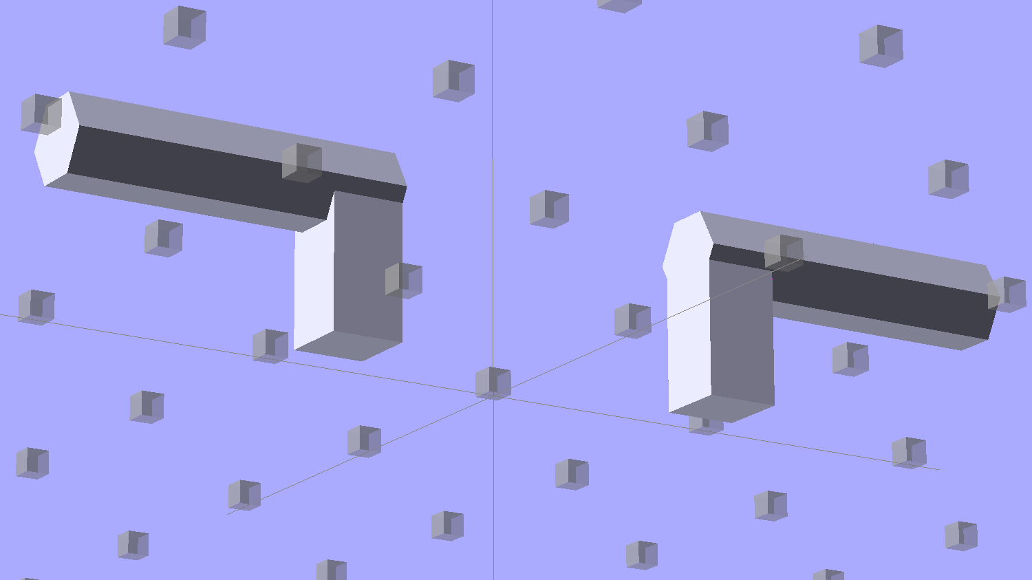
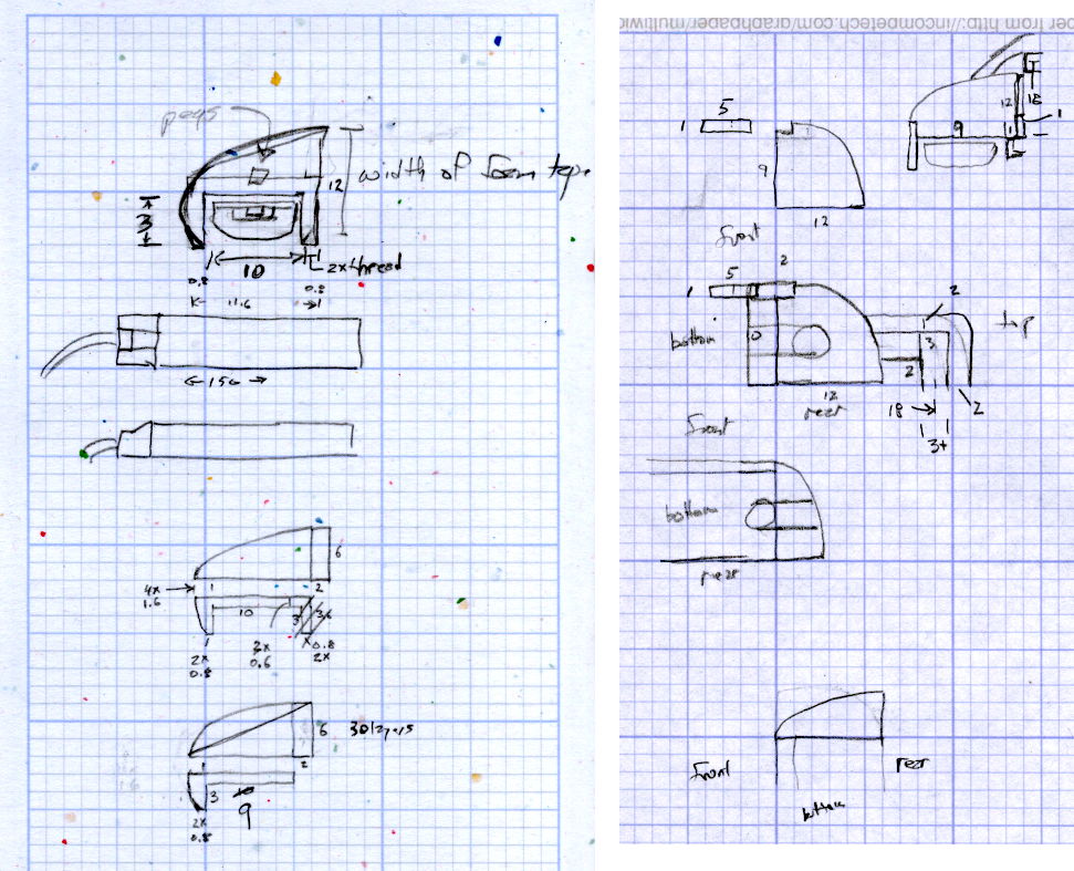
The original design doodles, which bear a vague resemblance to the final mounts:
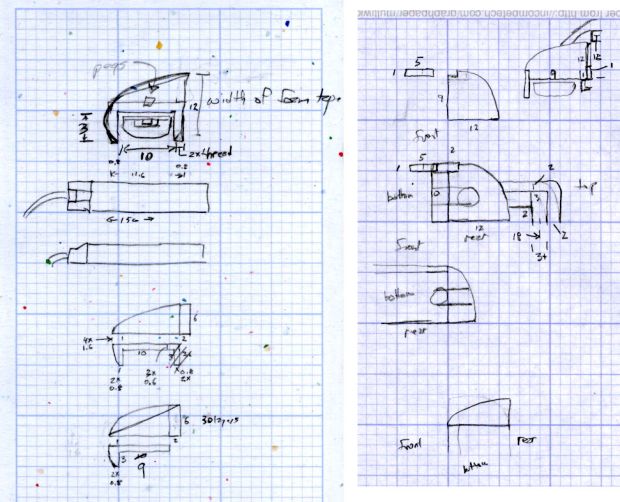
LED Strip Light Mounts – Original Design Sketches The little snood coming out of the top would hide a wire going through a hole drilled in the capital-S of “Sears” on the front panel, but I came to my senses long before implementing that idea…
-
Subscribe
Subscribed
Have a WordPress.com account? Log in now.

