-
Chocolate Molds: 3D Printed Positive Plate vs. Pourable Silicone
Based on the results of the Squidwrench molds, I tweaked Tux’s height-map image a bit:

Tux_Hi_Profile A Bash script driving an OpenSCAD program turns that into a single positive mold model:
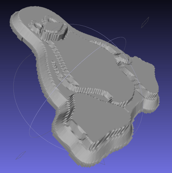
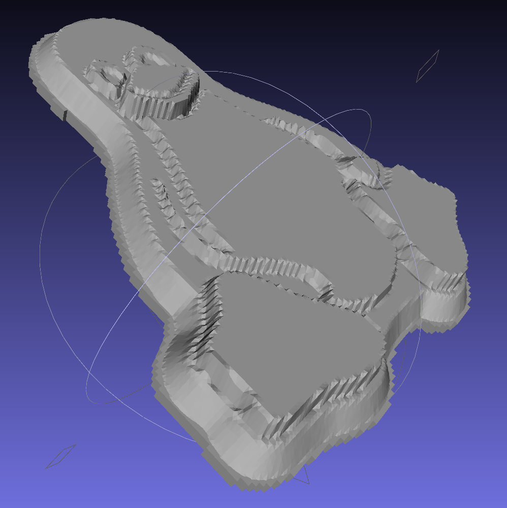
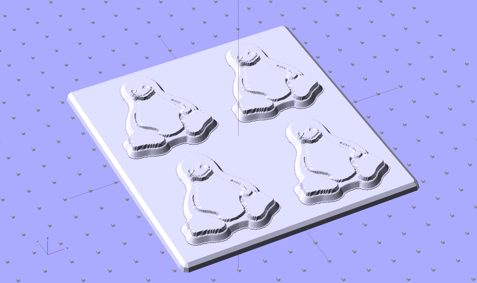
Tux_Hi_Profile – solid model Another OpenSCAD program arranges them in an array atop a baseplate:
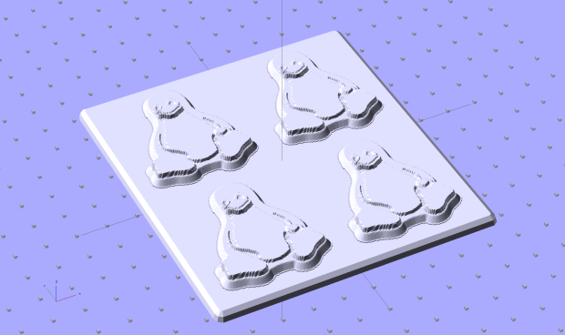
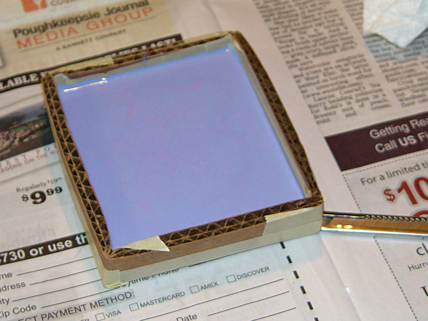
Tux Hi Profile – Framework 2×2 Pause an hour or so for 3D printing, tape a cardboard frame around it, then pour on a dollop of OOMOO 30 Tin-cure Silicone Rubber:
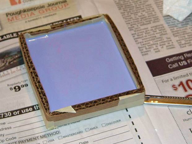
Tux 2×2 mold – curing A rough estimate of the volume and measurement thereof:
- Assume 1 cm slab thickness for mold cavities 4 or 5 mm deep
- Measure size of base plate in cm (given by OpenSCAD script in mm)
- Compute slab volume in cubic cm = millliliters (ignoring mold cavity volumes)
- Divide by 2 to find volume of each silicone component
- Mark that volume on the side of two sacrificial containers
- Pour silicone components into those containers
- Pour one into the other, mix twice as long as you think you should
- Scrupulously avoid cross-contaminating the original containers!
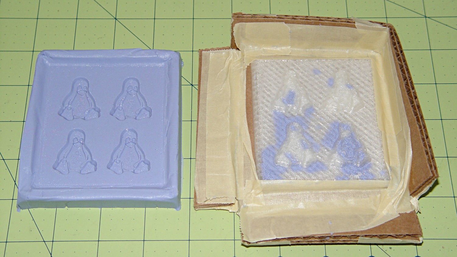
Fast-forward overnight, cut the tape, and peel the silicone negative off the positive:
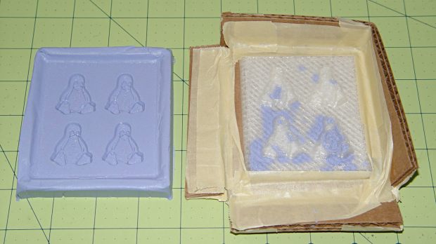
Tux 2×2 mold – opened The top surface of the 3D printed positive wasn’t completely
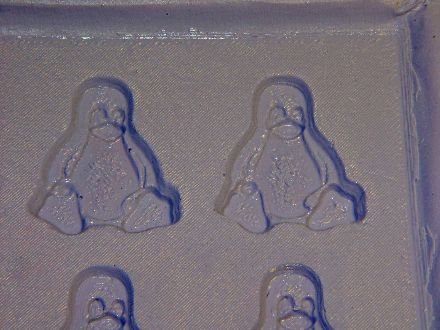
watersilicone-tight, so the silicone leaked through the top and filled part of the interior. No harm done, but I wasn’t expecting that. The interior of the silicone negative came out pretty well, although you can see some small bubble cavities that may be due to air leaking out through the top of the positive: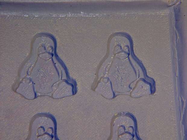
Tux 2×2 mold – negative detail The hand-knitted texture of the 3D printing process comes through very well, which is a Good Thing in this application. If you don’t like that, you can devote considerable time & attention to removing all traces of the production process.
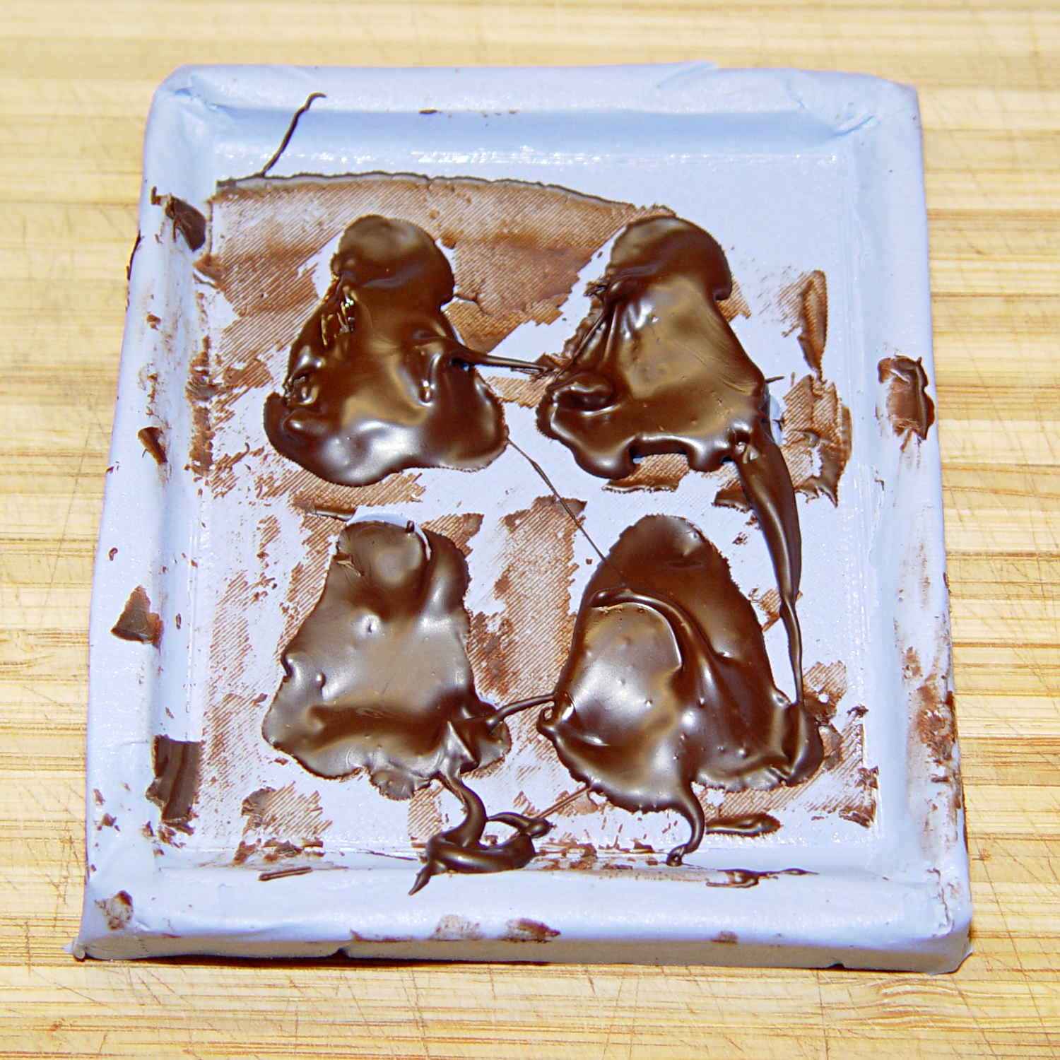
As a proof of concept, I melted and tempered four Dove Dark Chocolate Promises, then poured the chocolate into the cavities:
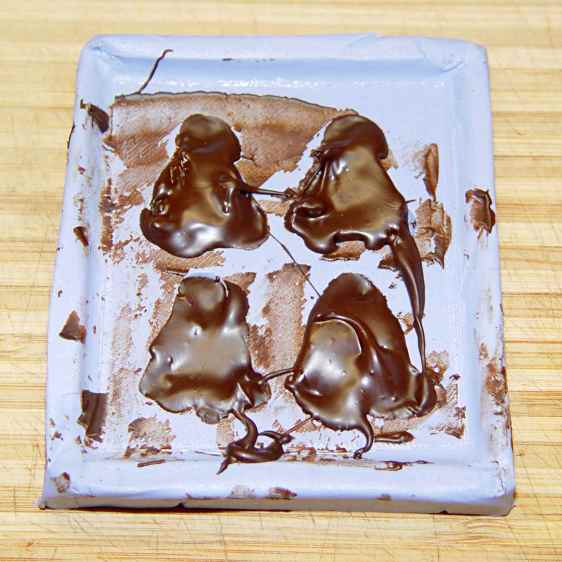
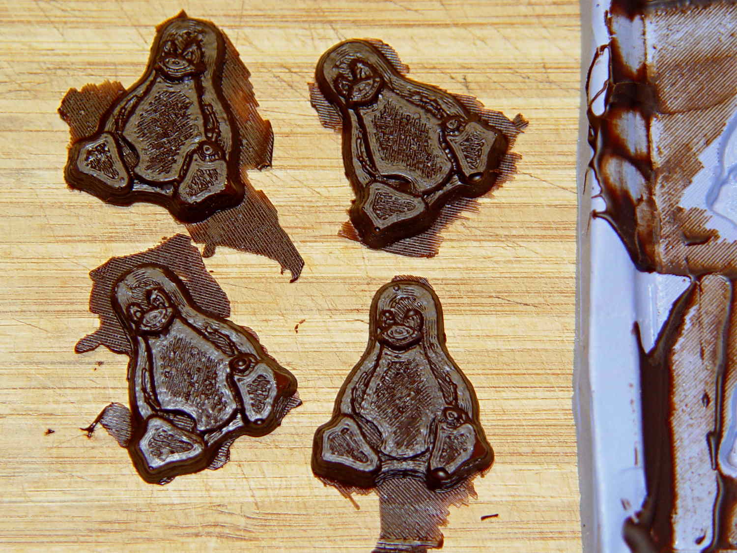
Tux 2×2 mold – filled The tempering followed a fairly simple process that worked reasonably well, but the chocolate obviously wasn’t liquid when I poured it. The results looked pretty good, in a textured sort of way:
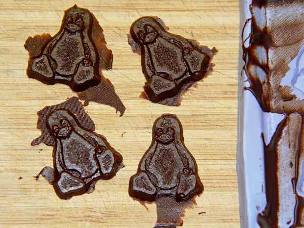
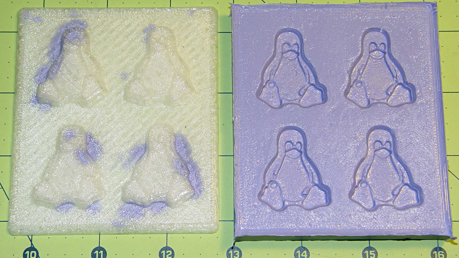
Tux chocolates – silicone mold Flushed with success, I tweaked the mold to eliminate the raised lip around the edge, printed another positive plate, mixed up more silicone rubber, paid more attention to getting rid of the bubbles, and got this result:
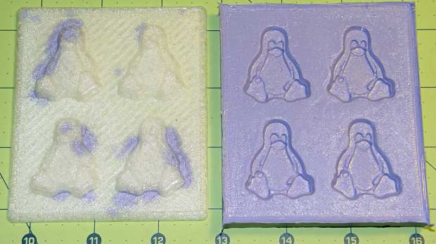
Tux 2×2 mold 2 – opened The printed surface still isn’t silicone-tight, which began to puzzle me, but the result looked pretty good.
After some fiddling around, though, I think printing the entire mold array isn’t the way to go. OpenSCAD can handle these 2×2 arrays, but a slightly tweaked Tux model (about which, more later) grossly increased the processing time and memory usage; OpenSCAD (and its CGAL geometry back end) filled all 4 GB of RAM, then blotted up 5 GB of swap space, ran for well over half an hour, and totally locked up the desktop UI for the duration.
It’s certainly infeasible to print the larger array on a sizable base plate that you’d need for a real project. I think printing multiple copies of a single model (duplicating them in the slicer, which is fast & easy), then attaching them to a plain base will work better. There’s no need to print the base plate, either, as a serrated top surface doesn’t buy anything; acrylic (or some such) sheet is cheap, flat, and readily available.
The Bash scripts and OpenSCAD programs below don’t produce exactly the same results you see above, mostly because I screwed around with them while discovering the reasons why doing it this way doesn’t make sense, but they can serve as a starting point if you must convince yourself, too.
This Bash script produces a single positive mold item from a height map image:
#!/bin/bash
DotsPerMM=3.0
MapHeight=4
ImageName="${1%%.*}"
rm ${ImageName}_* ${ImageName}-positive.stl
echo Prepare grayscale image...
#convert $1 -type Grayscale -depth 8 -trim +repage -flip +set comment ${ImageName}_prep.png
convert $1 -flip +set comment ${ImageName}_prep.png
echo Create PGM files...
convert ${ImageName}_prep.png -compress none ${ImageName}_map.pgm
convert ${ImageName}_prep.png -white-threshold 1 -compress none ${ImageName}_plate.pgm
echo Create height map data files...
ImageX=`identify -format '%[fx:w]' ${ImageName}_map.pgm`
ImageY=`identify -format '%[fx:h]' ${ImageName}_map.pgm`
echo Width: ${ImageX} x Height: ${ImageY}
cat ${ImageName}_map.pgm   | tr -s ' \012' '\012' | tail -n +5 | column -x -c $((8*$ImageX)) > ${ImageName}_map.dat
cat ${ImageName}_plate.pgm | tr -s ' \012' '\012' | tail -n +5 | column -x -c $((8*$ImageX)) > ${ImageName}_plate.dat
echo Create mold positive...
time openscad -D fnPlate=\"${ImageName}_plate.dat\" \
-D fnMap=\"${ImageName}_map.dat\" -D Height=$MapHeight \
-D ImageX=$ImageX -D ImageY=$ImageY -D DotsPerMM=$DotsPerMM \
-o ${ImageName}-positive.stl MoldPositive.scad
That script drives this OpenSCAD source code:
// Mold positive pattern from grayscale height map
// Ed Nisley KE4ZNU - March 2014 - adapted from cookie press, added alignment pins

//-----------------
// Mold files

fnMap = "Tux_map.dat";					// override with -D 'fnMap="whatever.dat"'
fnPlate = "Tux_plate.dat";				// override with -D 'fnPlate="whatever.dat"'

DotsPerMM = 3.0;						// overrride with -D DotsPerMM=number

MapHeight = 4.0;						// overrride with -D MapHeight=number

ImageX = 100;							// overrride with -D ImageX=whatever
ImageY = 100;

UsePins = true;

MapScaleXYZ = [1/DotsPerMM,1/DotsPerMM,MapHeight/255];
PlateScaleXYZ = [1/DotsPerMM,1/DotsPerMM,1.0];

echo("Press File: ",fnMap);
echo("Plate File: ",fnPlate);

echo(str("ImageX:",ImageX," ImageY: ", ImageY));
echo(str("Map Height: ",MapHeight));
echo(str("Dots/mm: ",DotsPerMM));
echo(str("Scale Map: ",MapScaleXYZ,"  Plate: ",PlateScaleXYZ));

//- Extrusion parameters - must match reality!

ThreadThick = 0.25;
ThreadWidth = 2.0 * ThreadThick;

//- Buid parameters

PlateThick = IntegerMultiple(1.0,ThreadThick);		// solid plate under press relief

PinOD = 1.75;				// locating pin diameter
PinDepth = PlateThick;		//  ... depth into bottom surface = total length/2
PinOC = 20.0;				// spacing within mold item

echo(str("Pin depth: ",PinDepth," spacing: ",PinOC));

//- Useful info

function IntegerMultiple(Size,Unit) = Unit * ceil(Size / Unit);

HoleWindage = 0.2;

Protrusion = 0.1;						// make holes & unions work correctly

MaxConvexity = 5;						// used for F5 previews in OpenSCAD GUI

ZFuzz = 0.2;							// numeric chaff just above height map Z=0 plane

//-----------------
// Import plate height map, slice off a slab to define outline

module Slab(Thick=1.0) {
	intersection() {
		translate([0,0,Thick/2])
			cube([2*ImageX,2*ImageY,Thick],center=true);
		scale(PlateScaleXYZ)
			difference() {
				translate([0,0,-ZFuzz])
					surface(fnPlate,center=true,convexity=MaxConvexity);
				translate([0,0,-1])
					cube([2*ImageX,2*ImageY,2],center=true);
			}
	}
}

//- Put peg grid on build surface

module ShowPegGrid(Space = 10.0,Size = 1.0) {

	Range = floor(50 / Space);

	for (x=[-Range:Range])
	  for (y=[-Range:Range])
		translate([x*Space,y*Space,Size/2])
			%cube(Size,center=true);
}

//-- convert cylinder to low-count polygon

module PolyCyl(Dia,Height,ForceSides=0) {			// based on nophead's polyholes

  Sides = (ForceSides != 0) ? ForceSides : (ceil(Dia) + 2);

  FixDia = Dia / cos(180/Sides);

  cylinder(r=(FixDia + HoleWindage)/2,
           h=Height,
	   $fn=Sides);
}

//-- Locating pin hole with glue recess
//  Default length is two pin diameters on each side of the split

module LocatingPin(Dia=PinOD,Len=0.0) {

	PinLen = (Len != 0.0) ? Len : (4*Dia);

	translate([0,0,-ThreadThick])
		PolyCyl((Dia + 2*ThreadWidth),2*ThreadThick,4);

	translate([0,0,-2*ThreadThick])
		PolyCyl((Dia + 1*ThreadWidth),4*ThreadThick,4);

	translate([0,0,-(Len/2 + ThreadThick)])
		PolyCyl(Dia,(Len + 2*ThreadThick),4);

}

//- Build it

//ShowPegGrid();

echo("Building mold");
union() {
	difference() {
		Slab(PlateThick + Protrusion);
		if (UsePins)
			for (i=[-1,1])
				translate([0,i*PinOC/2,0])
					rotate(180/4) LocatingPin(Len=2*PinDepth);
	}
	translate([0,0,PlateThick])							// cookie press height map
		scale(MapScaleXYZ)
		difference() {
			translate([0,0,-ZFuzz])
				surface(fnMap,center=true,convexity=MaxConvexity);
			translate([0,0,-1])
				cube([2*ImageX,2*ImageY,2],center=true);
		}
}
This OpenSCAD source code slides a base plate under an array of those mold items, with options for a separate plate using alignment pins or the combined plate-with-molds shown above:
// Positive mold framework for chocolate slabs
// Ed Nisley - KE4ZNU - March 2014

Layout = "FrameMolds";		// FramePins FrameMolds Pin

//- Extrusion parameters must match reality!
//  Print with 2 shells and 3 solid layers

ThreadThick = 0.20;
ThreadWidth = 0.40;

Protrusion = 0.1;			// make holes end cleanly

HoleWindage = 0.2;

//----------------------
// Dimensions

FileName = "Tux_Hi_Profile-positive.stl";	// overrride with -D

Molds = [2,2];					// count of molds within framework

MoldOC = [45.0,50.0];			// on-center spacing of molds
MoldSlab = 1.0;					// thickness of slab under molds

BaseThick = 3.0;

BaseSize = [(Molds[0]*MoldOC[0] + 0),(Molds[1]*MoldOC[1] + 0),BaseThick];
echo(str("Overall base: ",BaseSize));

PinOD = 1.75;					// locating pin diameter
PinLength = 2.0;				//  ... total length
PinOC = 20.0;				// spacing within mold item

//----------------------
// Useful routines

//- Put peg grid on build surface

module ShowPegGrid(Space = 10.0,Size = 1.0) {

	RangeX = floor(100 / Space);
	RangeY = floor(125 / Space);

	for (x=[-RangeX:RangeX])
		for (y=[-RangeY:RangeY])
			translate([x*Space,y*Space,Size/2])
			%cube(Size,center=true);

}

module PolyCyl(Dia,Height,ForceSides=0) {			// based on nophead's polyholes

  Sides = (ForceSides != 0) ? ForceSides : (ceil(Dia) + 2);

  FixDia = Dia / cos(180/Sides);

  cylinder(r=(FixDia + HoleWindage)/2,
           h=Height,
	   $fn=Sides);
}

// Locating pin hole with glue recess
//  Default length is two pin diameters on each side of the split

module LocatingPin(Dia=PinOD,Len=0.0) {

	PinLen = (Len != 0.0) ? Len : (4*Dia);

	translate([0,0,-ThreadThick])
		PolyCyl((Dia + 2*ThreadWidth),2*ThreadThick,4);

	translate([0,0,-2*ThreadThick])
		PolyCyl((Dia + 1*ThreadWidth),4*ThreadThick,4);

	translate([0,0,-(Len/2 + ThreadThick)])
		PolyCyl(Dia,(Len + 2*ThreadThick),4);

}

module LocatingPins(Length) {
	for (i=[-1,1])
	translate([0,i*PinOC/2,0])
		rotate(180/4)
		LocatingPin(Len=Length);
}

//-- import a single mold item

module MoldItem() {

//	intersection() {
		import(FileName,convexity=10);
//		cube([100,100,3],center=true);
//	}
}

//-- Overall frame shape

module Frame() {

//	translate([0,0,BaseSize[2]/2])		// platform under molds
//		cube(BaseSize,center=true);

	difference() {
		hull()
			for (i=[-1,1], j=[-1,1])
				translate([i*BaseSize[0]/2,j*BaseSize[1]/2,0])
					sphere(r=BaseThick);
		translate([0,0,-BaseThick])
			cube(2*BaseSize,center=true);
	}

}

//- Build it

ShowPegGrid();

if (Layout == "Pin")
	LocatingPin(Len=PinLength);

if (Layout == "Frame")
	Frame();

if (Layout == "FramePins")
	difference() {
		Frame();

		translate([-MoldOC[0]*(Molds[0] - 1)/2,-MoldOC[1]*(Molds[1] - 1)/2,0])
			for (i=[0:Molds[0]-1],j=[0:Molds[1]-1])
				translate([i*MoldOC[0],j*MoldOC[1],BaseSize[2]])
					LocatingPins(BaseThick);
	}

if (Layout == "FrameMolds") {
	Frame();
	translate([-MoldOC[0]*(Molds[0] - 1)/2,-MoldOC[1]*(Molds[1] - 1)/2,0])
		for (i=[0:Molds[0]-1],j=[0:Molds[1]-1])
			translate([i*MoldOC[0],j*MoldOC[1],BaseThick - MoldSlab + Protrusion])
			MoldItem();
}
-
Subscribe
Subscribed
Have a WordPress.com account? Log in now.

