-
Kenmore 158: NEMA 23 Motor Adapter
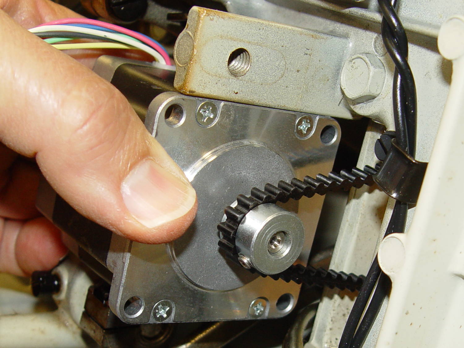
After removing the AC motor from the sewing machine, I wondered if a NEMA 23 stepper motor would fit:
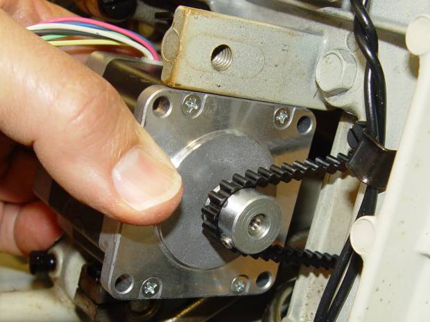
Kenmore 158 – NEMA 23 stepper – trial fit Huh. Who’d’a thunk it? That’s just too good to pass up…
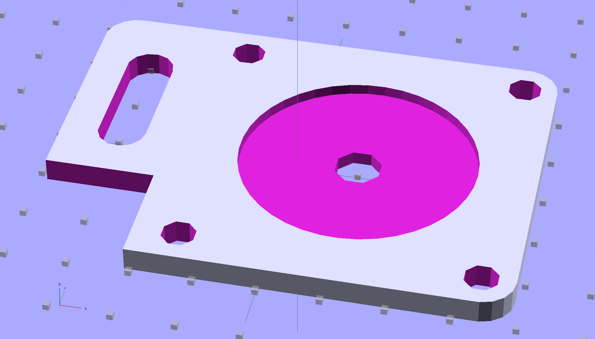
Although you wouldn’t use PLA for the real motor mount, this was easy:
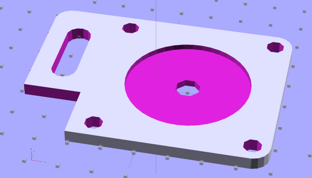
Drive Motor Mount – solid model And the whole affair fits pretty much like you’d expect:
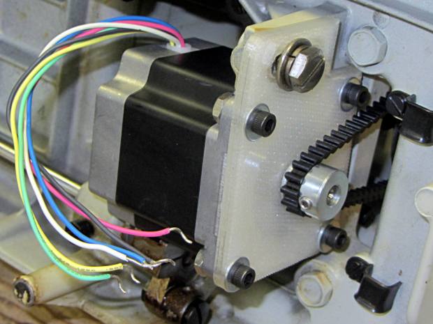
Kenmore 158 – NEMA 23 stepper – on adapter The NEMA 23 motor doesn’t have the same end profile as the AC motor and the adapter plate gets in the way of the pulley, but flipping the pulley end-for-end perfectly aligned the belt.
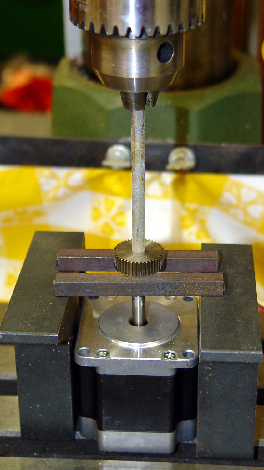
For whatever it’s worth, here’s how I removed the pressed-on gear from the shaft:
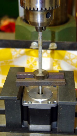
NEMA 23 Stepper – removing gear I’m pretty sure I have a little gear puller somewhere, but it’s not where I expected to find it, which means it could be anywhere.
Much to my astonishment, the shafts on both motors are exactly 1/4″ inch. I filed a flat on the shaft to avoid having the setscrew goober the poor thing.
A stepper isn’t the right hammer for this job, because it can’t possibly reach 8000 rpm, but it’ll be good enough to explore the parameter space and weed out the truly stupid mistakes. A brushless DC motor from halfway around the planet would fit in the same spot.
The OpenSCAD source code:
// NEMA 23 Stepper Mounting Plate
// Ed Nisley - KE4ZNU - June 2014

Layout = "Build";			// Build Show

//- Extrusion parameters must match reality!
//  Print with 4 shells and 3 solid layers

ThreadThick = 0.20;
ThreadWidth = 0.40;

HoleWindage = 0.2;			// extra clearance

Protrusion = 0.1;			// make holes end cleanly

AlignPinOD = 1.70;			// assembly alignment pins: filament dia

inch = 25.4;

function IntegerMultiple(Size,Unit) = Unit * ceil(Size / Unit);

//----------------------
// Dimensions
// Origin at bottom front corner of plate as mounted on machine
//	motor mounted on rear surface, so recess is on that side

PlateThick = 4.0;				// overall plate thickness

SlotOffset = [10.0,13.0,0];		// center nearest origin, motor in X+,Y+ direction
SlotSize = [8.0,25.0];			// diameter of mounting screw , overall end-to-end length

CutoutOffset = [0.0,40.0,0];	// cutout around machine casting
CutoutSize = [18.0,18.0];

MotorBase = 58.0;				// square base plate side
MotorHoleOC = 47.2;				// hole center-to-center spacing
MotorHoleOffset = MotorHoleOC/2;
MotorHoleDia = 5.0;
MotorBaseCornerRadius = (MotorBase - MotorHoleOC)/2;

FlangeWidth = 20.0;				// mounting flange

MotorCenter = [(FlangeWidth + MotorBase/2),(MotorBase/2),0];		// XY of shaft centerline

MotorShaftDia = 7.0;			// allow some clearance

HubDia = 38.5;					// allow some clearance
HubHeight = 1.8;

//----------------------
// Useful routines

module PolyCyl(Dia,Height,ForceSides=0) {			// based on nophead's polyholes

  Sides = (ForceSides != 0) ? ForceSides : (ceil(Dia) + 2);

  FixDia = Dia / cos(180/Sides);

  cylinder(r=(FixDia + HoleWindage)/2,
           h=Height,
           $fn=Sides);
}

module ShowPegGrid(Space = 10.0,Size = 1.0) {

  RangeX = floor(100 / Space);
  RangeY = floor(125 / Space);

	for (x=[-RangeX:RangeX])
	  for (y=[-RangeY:RangeY])
		translate([x*Space,y*Space,Size/2])
		  %cube(Size,center=true);

}

//----------------------
// Build it!

module BasePlate() {

	difference() {
//		cube([(MotorCenter[0] + MotorBase/2),MotorBase,PlateThick],center=false);
		linear_extrude(height = PlateThick) {
			hull() {
				translate([MotorBaseCornerRadius,MotorBaseCornerRadius])
					circle(r=MotorBaseCornerRadius);
				translate([MotorBaseCornerRadius,MotorBase - MotorBaseCornerRadius])
					circle(r=MotorBaseCornerRadius);
				translate([FlangeWidth + MotorBase - MotorBaseCornerRadius,MotorBase - MotorBaseCornerRadius])
					circle(r=MotorBaseCornerRadius);
				translate([FlangeWidth + MotorBase - MotorBaseCornerRadius,MotorBaseCornerRadius])
					circle(r=MotorBaseCornerRadius);
			}
		}

		translate(MotorCenter - [0,0,Protrusion]) {
			rotate(180/8)
				PolyCyl(MotorShaftDia,(PlateThick + 2*Protrusion),8);		// shaft hole
			PolyCyl(HubDia,(HubHeight + Protrusion));						// hub recess
			for (x=[-1,1] , y=[-1,1]) {
				translate([x*MotorHoleOffset,y*MotorHoleOffset,0])
					rotate(180/8)
						PolyCyl(MotorHoleDia,(PlateThick + 2*Protrusion),8);
			}
		}

		translate(SlotOffset - [0,0,Protrusion]) {							// adjustment slot
			linear_extrude(height = (PlateThick + 2*Protrusion))
				hull() {
					circle(d=SlotSize[0]);
					translate([0,(SlotSize[1] - SlotSize[0])])
						circle(d=SlotSize[0]);

				}
		}

		translate(CutoutOffset - [Protrusion,0,Protrusion])
			linear_extrude(height = (PlateThick + 2*Protrusion))
				square(CutoutSize + [Protrusion,Protrusion]);
	}
}

ShowPegGrid();

if (Layout == "Show") {
	BasePlate();
}

if (Layout == "Build") {
	translate([-(SlotOffset[0] + MotorBase/2),MotorBase/2,PlateThick])
		rotate([180,0,0])
			BasePlate();
}

-
Subscribe
Subscribed
Have a WordPress.com account? Log in now.

