-
Kenmore 158: Hall Effect Speed Control Output vs. Pedal Depression
For lack of anything smarter, I marked the Kenmore 158 pedal’s range of motion in 2 mm increments, starting at the top:
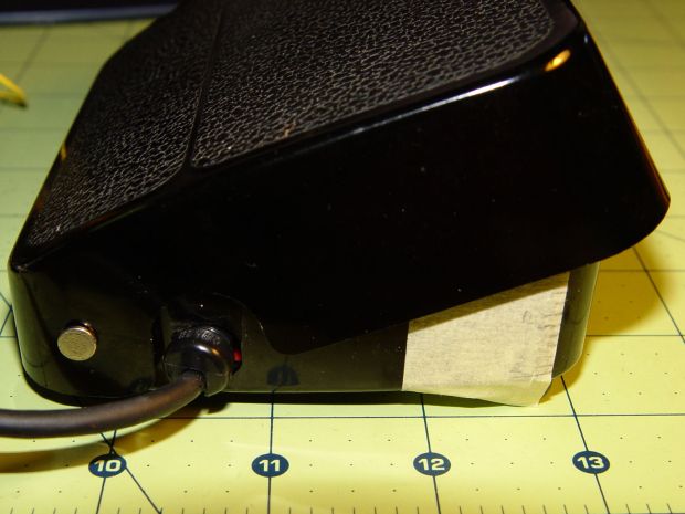
Kenmore 158 foot pedal – motion calibration With the Hall effect sensor connected to a +5 V supply, the output looks like this:
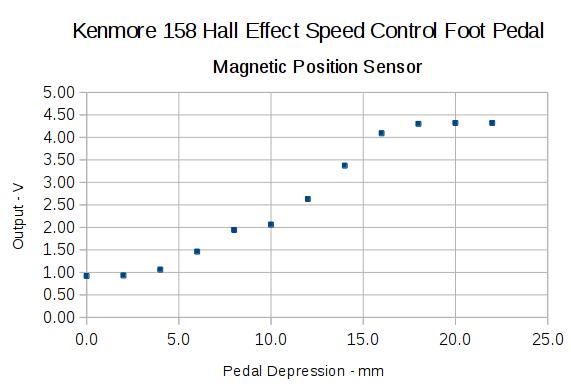
Hall sensor output vs pedal depression The point at 10 mm looks a bit out of place; other than that, the curve is about what you’d expect. The sensor saturates at about 0.84 V and 4.4 V, more or less, so you’re seeing the bias magnet on the low end and the main magnet on the high end.
Obviously, you shouldn’t take these measurements too seriously, but they’re in the right ballpark.
The pivot pin is 75 mm from the base of that line, so the subtended angle is more-or-less 16° = arctan(22/75), which is small enough that plotting the results as a function of the pedal angle doesn’t look any different.
Although you could linearize that, I think the curve has the right shape for a foot pedal speed control: it starts slowly and tapers off smoothly at the high end.
I think I could add a few more millimeters of magnet travel, but this will certainly suffice to get the crash test dummy running.
-
Subscribe
Subscribed
Have a WordPress.com account? Log in now.

