-
ET227 Transistor Heatsink: Angled Blower Mount
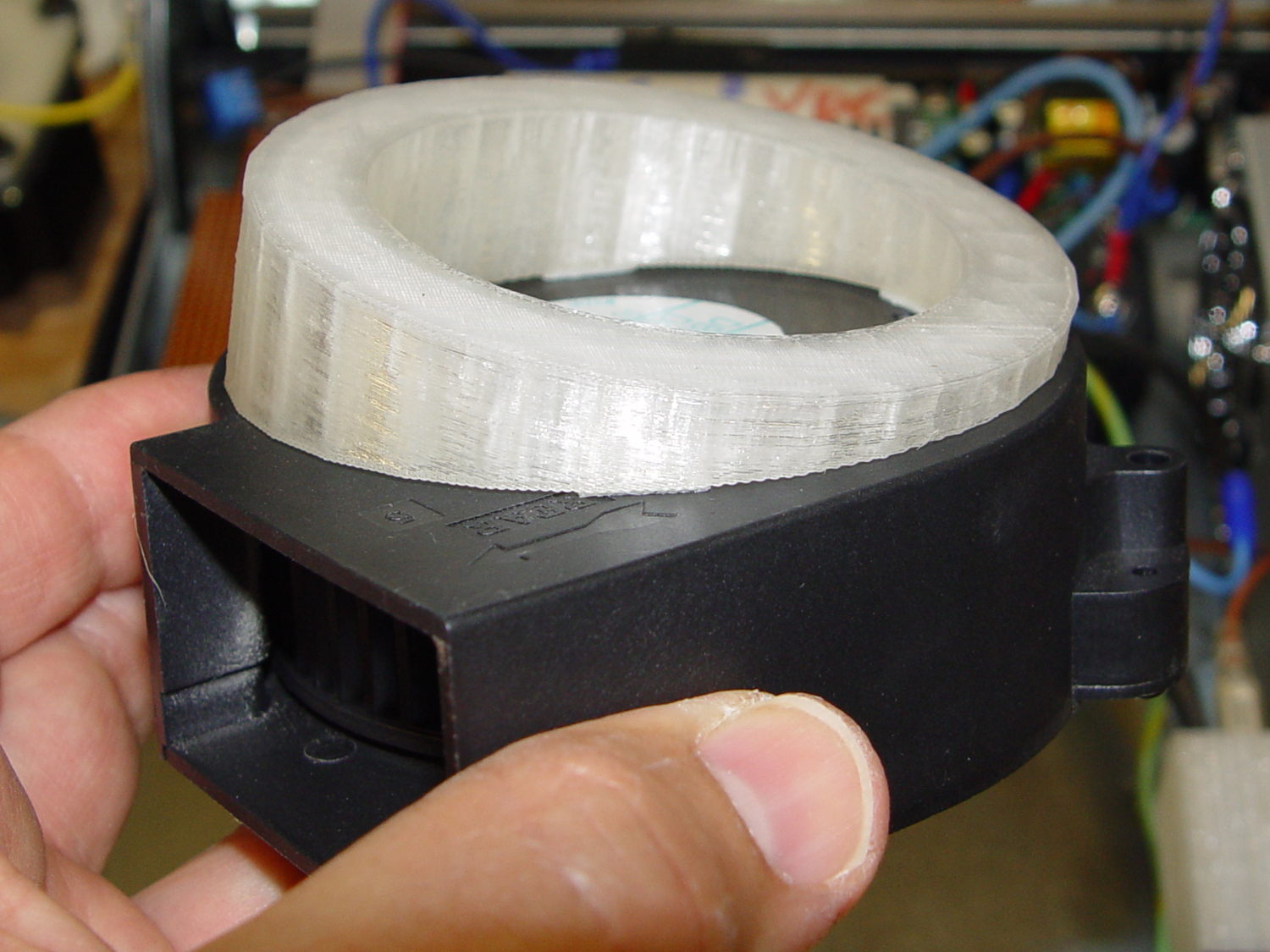
This angled ring fits under a repurposed CPU cooler:
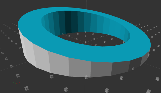
Blower Mount – solid model Viewed perpendicular to the angled surface, it’s a circle, so what looks like a vertical cylinder is actually slightly oval to make the top come out right. That way, the walls are vertical, not angled, and it doesn’t stand crooked on the base plate.
Such a shape is trivially easy for a 3D printer:
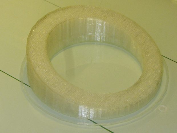
Blower mount – on build platform And looks about like you’d expect on the blower, which is why that surface must be a circle:
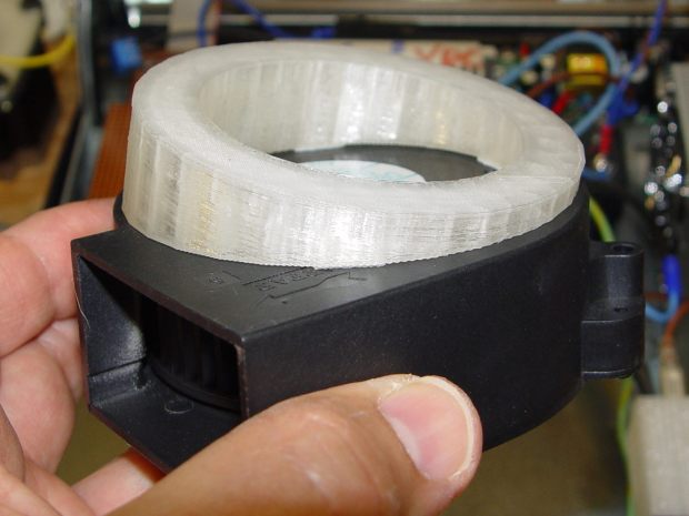
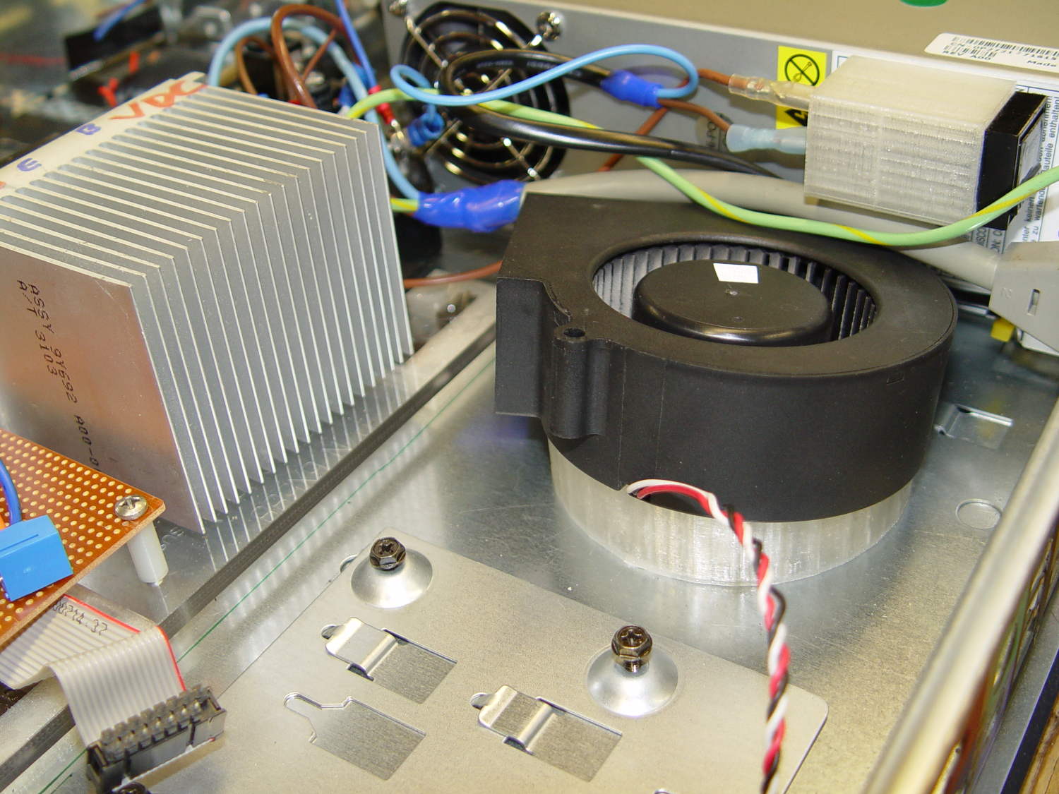
Blower Mount – bottom view A trial fit in the case, along with a bunch of parts I haven’t written up yet:
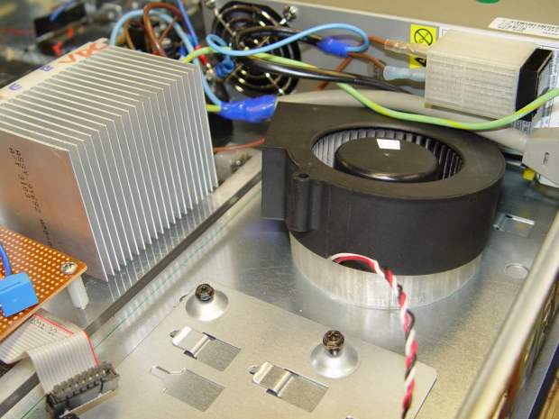
Blower Mount – installed Under normal circumstances, you’d want the blower a bit higher and level, but there just wasn’t anywhere else to fit the fuseholder. Besides, this way the airflow goes slightly upward toward the clearance over the top of that monster heatsink. Some air flows along the side of the heatsink to cool the isolated power supply you can’t quite see in the far corner of the chassis beyond that tangle of wires.
The angle seems pretty close to right, although I must get the rest of the circuitry running to know if the airflow can actually transfer the heat from the heatsink out of the case.
It doesn’t take much OpenSCAD source code to define the shape:
// Blower mount
// Ed Nisley - KE4ZNU - August 2014

//- Extrusion parameters must match reality!

ThreadThick = 0.20;
ThreadWidth = 0.40;

HoleWindage = 0.2;			// extra clearance

Protrusion = 0.1;			// make holes end cleanly

AlignPinOD = 1.70;			// assembly alignment pins: filament dia

function IntegerMultiple(Size,Unit) = Unit * ceil(Size / Unit);

//----------------------
// Dimensions

MountOD = 85.0;						// a bit smaller than the housing OD

MountID = 60.0;						// carve out to reduce printing time

Base = 5.0;							// minimum thickness (allowing for some overhang)

ElevationAngle = atan(20/90);		// net tilt across fan base

ElevationDelta = MountOD * tan(ElevationAngle);

echo(str("Elevation angle: ",ElevationAngle," delta: ",ElevationDelta));

//----------------------
// Useful routines

module PolyCyl(Dia,Height,ForceSides=0) {			// based on nophead's polyholes

  Sides = (ForceSides != 0) ? ForceSides : (ceil(Dia) + 2);

  FixDia = Dia / cos(180/Sides);

  cylinder(r=(FixDia + HoleWindage)/2,
           h=Height,
           $fn=Sides);
}

module ShowPegGrid(Space = 10.0,Size = 1.0) {

  RangeX = floor(100 / Space);
  RangeY = floor(125 / Space);

	for (x=[-RangeX:RangeX])
	  for (y=[-RangeY:RangeY])
		translate([x*Space,y*Space,Size/2])
		  %cube(Size,center=true);

}

//----------------------
// Build it

ShowPegGrid();

difference() {
	scale([1,cos(ElevationAngle),1])
		cylinder(d=MountOD,h=Base + ElevationDelta);
	translate([-MountOD,-MountOD/2,Base])
		rotate([ElevationAngle,0,0])
			cube([2*MountOD,2*MountOD,ElevationDelta],center=false);
	translate([0,0,-Protrusion])
		cylinder(d=MountID,h=Base + 3*ElevationDelta);
}


-
Subscribe
Subscribed
Have a WordPress.com account? Log in now.

