-
ATX Power Supply: System Board Connector Bracket
The GX270 case contains a perfectly serviceable ATX power supply that can power all the bits & pieces that don’t run directly from the AC power line. I torched the connector off the system board, but there’s no practical way to mount it standing up through the prototyping board I’m using for the low voltage electronics. This bracket surrounds that connector and holds it at right angles to the board, with a pair of screws clamping it in place:
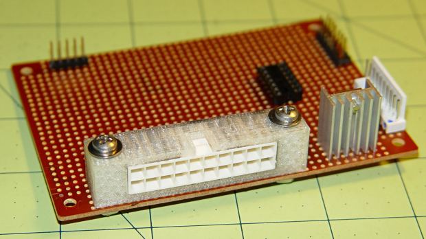
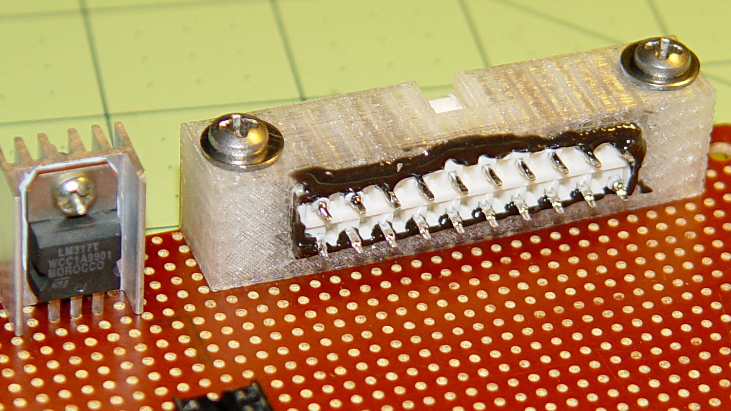
ATX Connector Bracket – front I invoked the shade of Willy McCoy, slashed the outside of the connector with a razor knife, buttered it up with epoxy, and shoved it flush inside the adapter. That messy epoxy bead around the joint should prevent it from pulling out to the front:
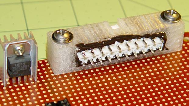
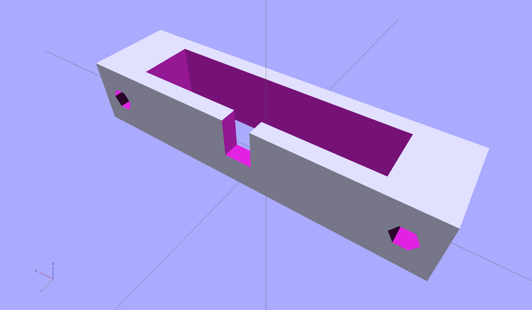
ATX Connector Bracket – rear The solid model looks like you’d expect:
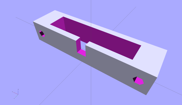
ATX Connector Mount In the unlikely event you need one, make sure the slot clears the locking clip on your ATX connector, as they differ between (at least) the 20 and 24 pin versions. This is actually a split 20/24 connector, with the smaller connector terminating elsewhere to power the LED strips.
The OpenSCAD source code:
// ATX power supply connector mounting bracket
// Ed Nisley - KE4ZNU - September 2014

//- Extrusion parameters must match reality!

ThreadThick = 0.20;
ThreadWidth = 0.40;

HoleWindage = 0.2;			// extra clearance

Protrusion = 0.1;			// make holes end cleanly

AlignPinOD = 1.70;			// assembly alignment pins: filament dia

function IntegerMultiple(Size,Unit) = Unit * ceil(Size / Unit);

//----------------------
// Dimensions

Screw = [3.5,7.0];						// mounting screws
OD = 0;
HEAD_OD = 1;

Wall = 3.0;

ATX = [43.5,9.75,12.0];					// connector outline

Shell = ATX + [2*(2*Wall + Screw[OD]),2*Wall,0.0];	// mount outline

Latch = [5.0,5.0,7.0];							// latch overlay

ScrewOC = ATX[0] + Screw[OD] + 2*Wall;

echo(str("Screw OC: ",ScrewOC," mm"));

//----------------------
// Useful routines

module PolyCyl(Dia,Height,ForceSides=0) {			// based on nophead's polyholes

  Sides = (ForceSides != 0) ? ForceSides : (ceil(Dia) + 2);

  FixDia = Dia / cos(180/Sides);

  cylinder(r=(FixDia + HoleWindage)/2,
           h=Height,
           $fn=Sides);
}

module ShowPegGrid(Space = 10.0,Size = 1.0) {

  RangeX = floor(100 / Space);
  RangeY = floor(125 / Space);

	for (x=[-RangeX:RangeX])
	  for (y=[-RangeY:RangeY])
		translate([x*Space,y*Space,Size/2])
		  %cube(Size,center=true);

}

ShowPegGrid();

difference() {
	translate([0,0,Shell[2]/2])						// mount shell
		cube(Shell,center=true);
	translate([0,0,ATX[2]/2])					// connector shell
		cube(ATX + [0,0,2*Protrusion],center=true);

	translate([0,(Latch[1]/2 + ATX[1]/2 - Protrusion),(-Latch[2]/2 + Shell[2])])
		cube(Latch + [0,Protrusion,Protrusion],center=true);

	for (i=[-1,1])
		translate([i*ScrewOC/2,(Shell[1]/2 + Protrusion),Shell[2]/2])
			rotate([90,0,0])
				PolyCyl(Screw[OD],(Shell[1] + 2*Protrusion));

}

-
Subscribe
Subscribed
Have a WordPress.com account? Log in now.

