-
Motor RPM Sensor Mounting: Bracket Madness
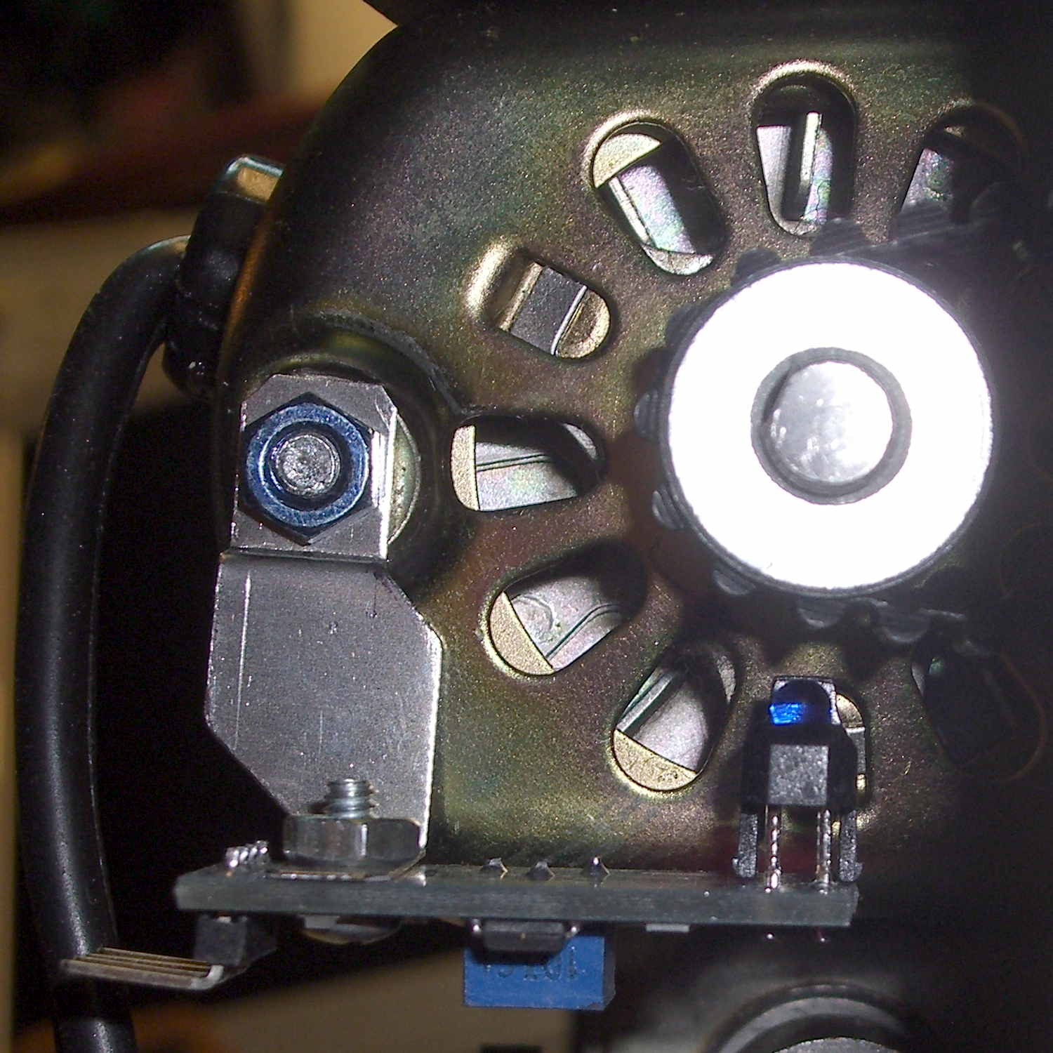
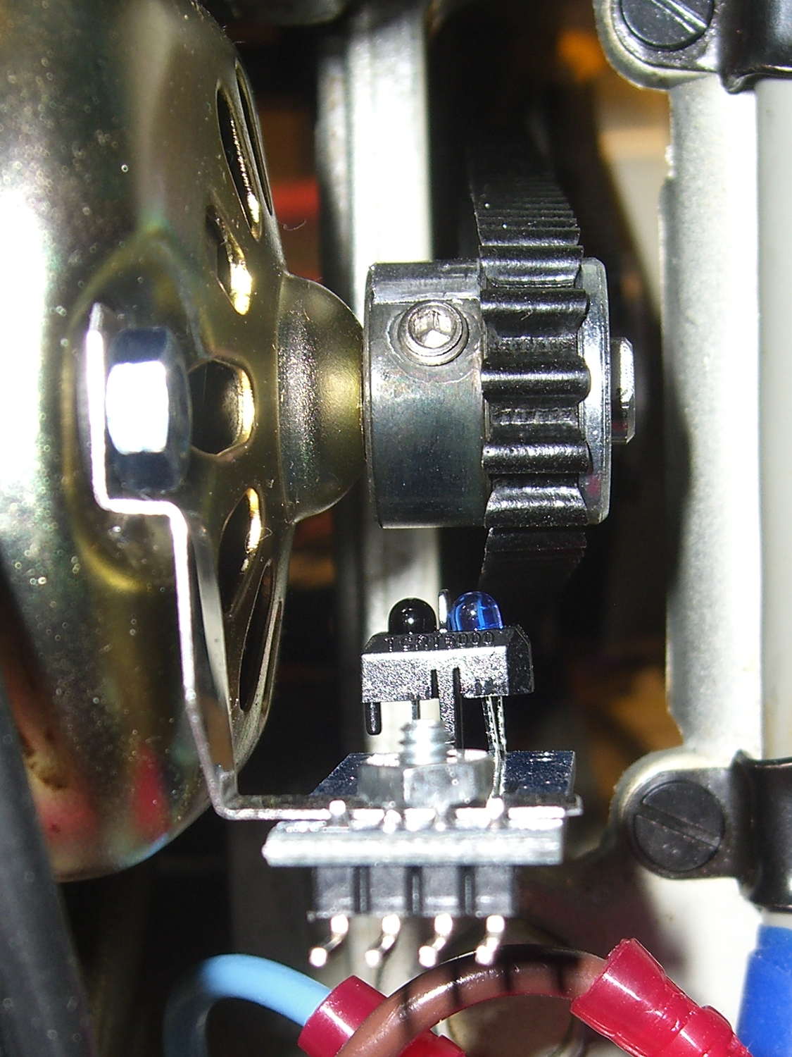
The first sensor bracket came from the scrap pile, but showed that it would produce 1/rev pulses from the motor shaft pulley. The positioning wasn’t quite right, so I made another bracket that put the TCRT5000 sensor at right angles to the pulley:
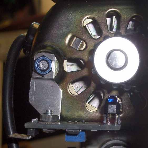
TCTR5000 Motor RPM Sensor – end view All of the sensors have a rakish tilt over their PCB, so at some point I must resolder them:
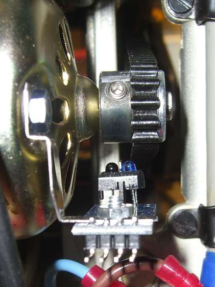
TCTR5000 Motor RPM Sensor – side view It might not matter, as the phototransistor on the left peers directly at the pulley, with the LED on the right acting as a floodlight.
“Made another bracket” sounds like the metal sprang fully formed from the concept. Herewith, the early contestants atop a sketch and the flat layout for The Ultimate Bracket:
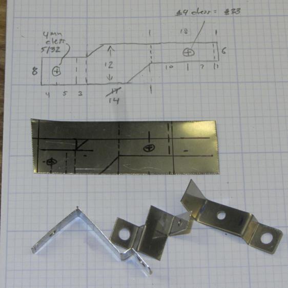
Motor RPM Sensor Brackets A closer look at that final dimension sketch, because I’ll need it again:

RPM Bracket Dimensions The vertical size of the center section (12 mm) sets the perpendicular distance of the sensor from the shaft. The horizontal size (14 mm) controls the pulley-to-sensor spacing.
The horizontal distance from the center section to the hole on the right (10 mm) adjusts the sensor spacing parallel to the shaft.
I cut the overall rectangle with tin snips, drilled & cleaned the holes, applied a nibbling tool to the details, trimmed the corners, filed off sharp edges & spines, and it was all good.
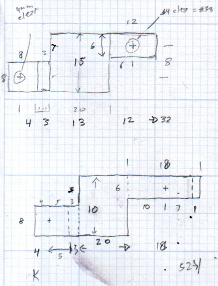
The doodles for the first few attempts, as I don’t want to repeat those mistakes:
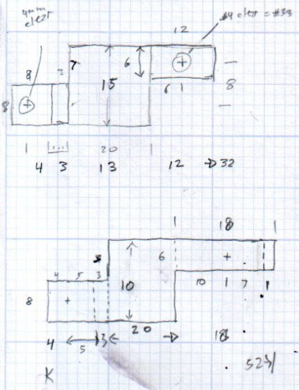
Bracket Doodles All in all, a few more hours of Quality Shop Time than I expected…

-
Subscribe
Subscribed
Have a WordPress.com account? Log in now.

