-
Kenmore 158: Shaft Position Sensor
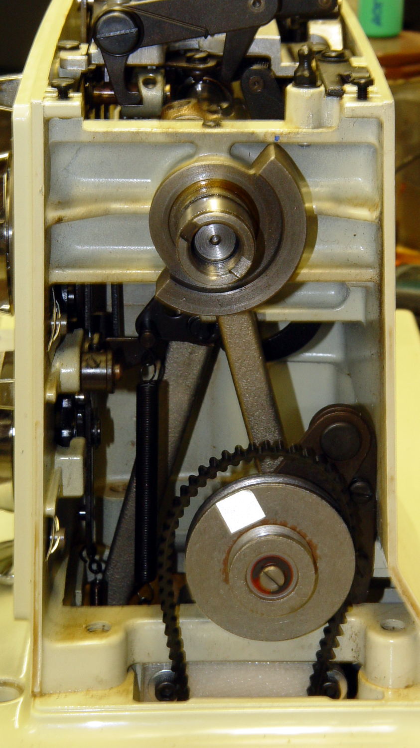
In order to stop the sewing machine with the needle either up or down, the controller must know the angular position of the main shaft. Fortunately, the shaft has a counterweight in a not-too-inconvenient location behind the handwheel:
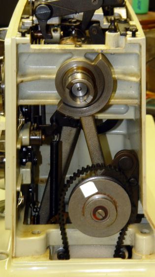
Kenmore 158 – main shaft counterweight The needle is fully down with the shaft in that position. I originally thought about putting a pair of sensors adjacent to the lower edge, but because the motor can rotate the shaft only counterclockwise (as seen from this end), watching a single sensor tells you everything you need to know:
- Falling edge: needle at top
- Rising edge: needle at bottom
N.B.: Although you can rotate the shaft backwards by hand, the controller needs to know the position only when stopping.
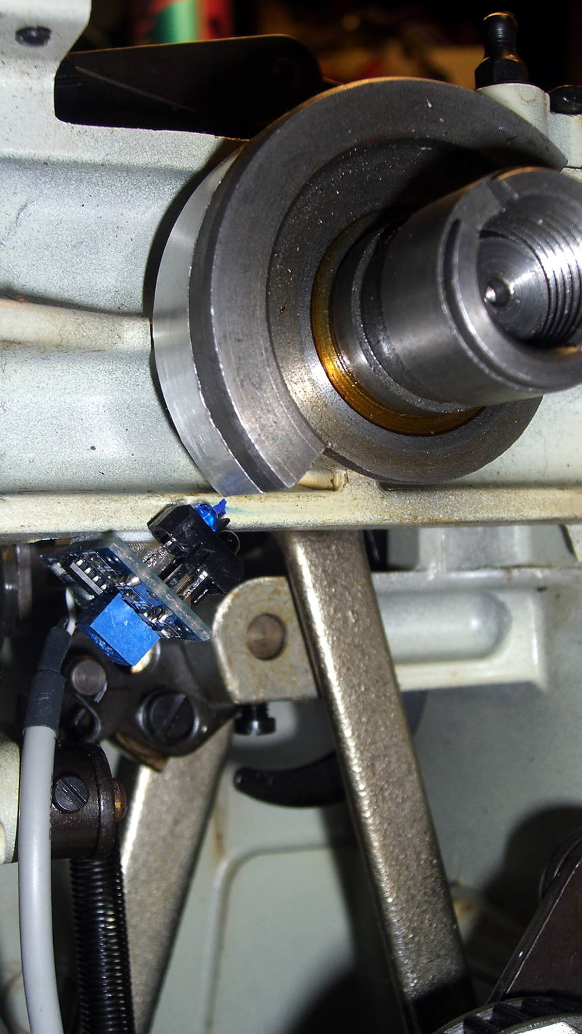
Some fiddling around showed that a TCRT5000 sensor board would fit neatly below the frame cross flange at exactly the right spot:
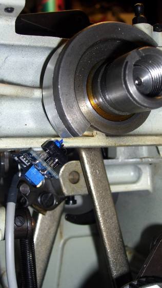
Shaft position sensor – in place The counterweight now sports a strip of stainless steel tape (normally used on HVAC ductwork) burnished to a high shine:
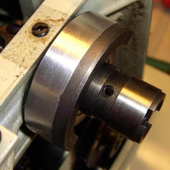
Kenmore 158 Shaft Counterweight – burnished steel tape The tape tucks around the counterweight to keep the wind out of its hair:
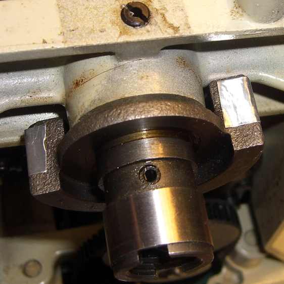
Kenmore 158 Shaft Counterweight – steel tape ends The handwheel spins on that smooth ring near the end of the shaft and covers the outer half of the counterweight, so the tape brightens up the only part of the counterweight that the sensor can see.
The sensor mounts on a fiddly bit of plastic that’s ideally suited for 3D printing:
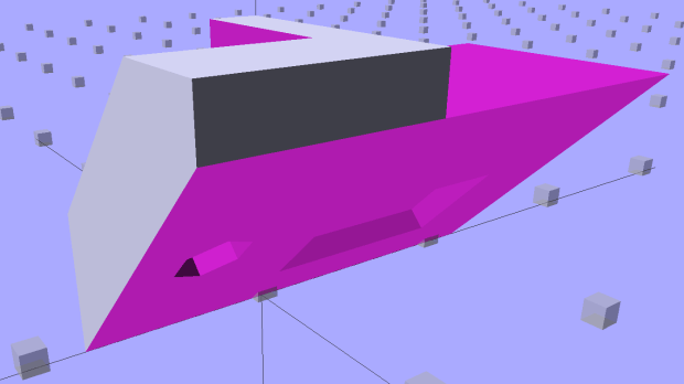
Shaft Position Sensor Mount – left The rectangular recess fits around the protruding trimpot leads, a screw in the hole fastens the sensor, the flange on the top fits against the inside edge of the frame flange to position the sensor head axially along the shaft, and the cutout to the left rear clears the whirling crank bearing on the shaft.
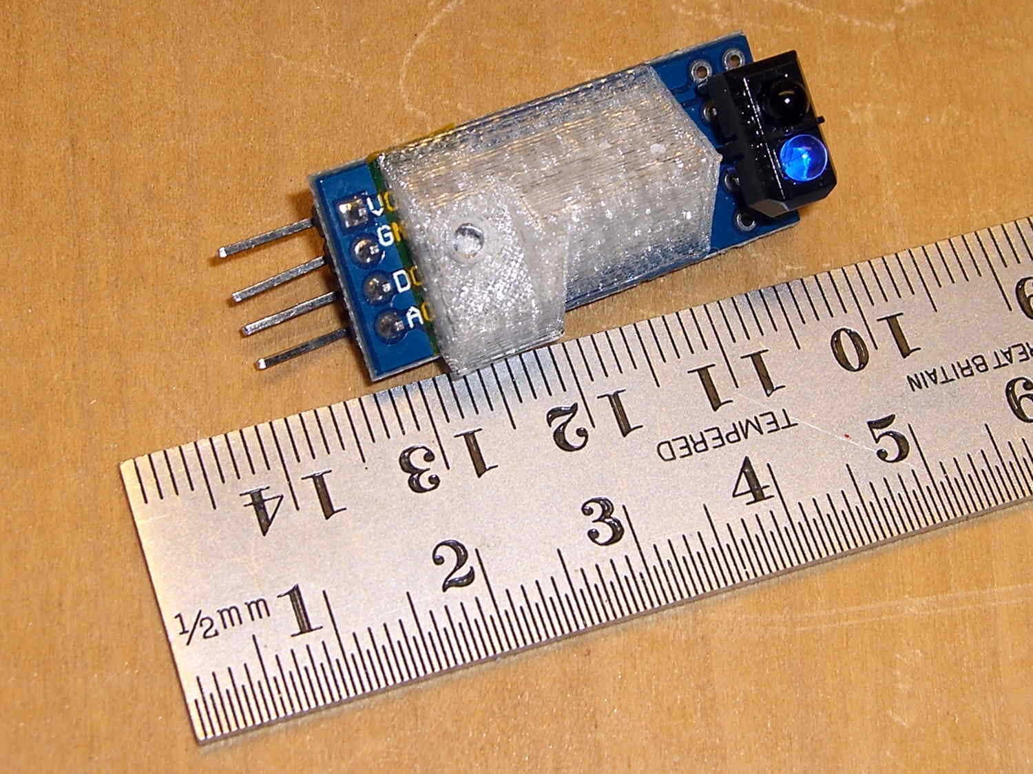
It looked good on the bench:
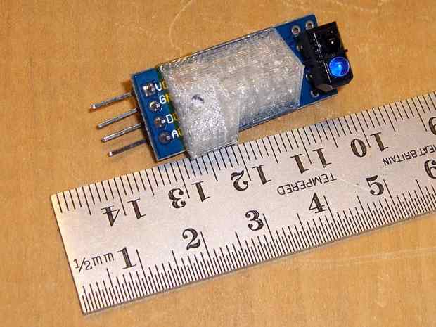
Shaft sensor mount – trial fit Rather than mess around with more connectors, I removed the pins and soldered a hank of CD-ROM audio cable (remember CD-ROMs?) directly into the top three holes.
After scrubulating the bottom of the frame flange with denatured alcohol, a square of double-stick foam tape holds the mount to the frame, eyeballometrically aligned to the proper position:
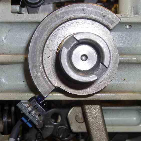
Kenmore 158 Shaft position sensor – end view That may be slightly too close to the counterweight, as the ideal distance is about 2 mm. The source code can add a shim that moves the mounting plane straight down, allowing the whole thing to move slightly to the left: increase the clearance while maintaining the same angular position. The next version will have a 1 mm
BaseShimand we’ll see how that goes.You could mirror the mount to put another sensor at the quadrature position on the right side of the counterweight.
It’s getting closer to becoming a simple matter of software…
The OpenSCAD source code:
// Shaft Position Sensor Mount
// Ed Nisley - KE4ZNU - October 2014

Layout = "Show";

//- Extrusion parameters must match reality!

ThreadThick = 0.20;
ThreadWidth = 0.40;

HoleWindage = 0.2;			// extra clearance

Protrusion = 0.1;			// make holes end cleanly

AlignPinOD = 1.70;			// assembly alignment pins: filament dia

function IntegerMultiple(Size,Unit) = Unit * ceil(Size / Unit);

//----------------------
// Dimensions

SensorWidth = 14.0;			// sensor PCB width
SensorLength = 21.0;		//  ... contact patch length
NumSensors = 1;

SensorScrewOffset = 5.0;	//  ... mounting hole to frame edge

PotLeads = [5.0,8.0,1.0];	// trimpot lead recess
PotOffset = [-1.5,8.5,0];

SensorScrewHeadOD = 6.0;	//  ... mounting screw head dia
SensorScrewTap = 2.25;		//  ... screw tap diameter
SensorScrewLength = 4.0;	//  ... screw length inside block

BaseShim = 1.0;				// additional height to align sensors
BaseAngle = 45;				// downward from horizontal

BaseSensors = NumSensors*SensorWidth;		// length along slanted top

BaseLength = BaseSensors*cos(BaseAngle);
BaseHeight = BaseSensors*sin(BaseAngle);

echo(str("Angle: ",BaseAngle," Height: ",BaseHeight," Length: ",BaseLength));

FrameWidth = 13.0;			// machine frame width

LipHeight = 3.0;			// locates part on frame to position sensors
LipWidth = IntegerMultiple(2.0,ThreadWidth);

Block = [BaseLength,
		 (FrameWidth + SensorScrewOffset + SensorScrewHeadOD/2),
		 (BaseHeight + BaseShim + LipHeight)];

echo(str("Block size: ",Block));

//----------------------
// Useful routines

module PolyCyl(Dia,Height,ForceSides=0) {			// based on nophead's polyholes

  Sides = (ForceSides != 0) ? ForceSides : (ceil(Dia) + 2);

  FixDia = Dia / cos(180/Sides);

  cylinder(r=(FixDia + HoleWindage)/2,
           h=Height,
           $fn=Sides);
}

module ShowPegGrid(Space = 10.0,Size = 1.0) {

  RangeX = floor(100 / Space);
  RangeY = floor(125 / Space);

	for (x=[-RangeX:RangeX])
	  for (y=[-RangeY:RangeY])
		translate([x*Space,y*Space,Size/2])
		  %cube(Size,center=true);

}

//-- Build the sensor mount

module SensorMount() {

	difference() {
		translate([0,(FrameWidth - Block[1]),0])
			cube(Block);

		translate([-Block[0],0,(Block[2] - LipHeight)])		// machine frame
			cube([3*Block[0],(FrameWidth + Protrusion),Block[2]]);

		translate([0,-Block[1]/2,0])						// sensor angle
			rotate([0,(90 - BaseAngle),0])
				cube(2*Block);

		translate([-SensorScrewLength/cos(90 - BaseAngle),-(2*Block[1] + LipWidth),0])
			rotate([0,-BaseAngle,0])						// remove all but lip on crank side
				cube(2*Block);

		for (i=[0:(NumSensors - 1)])						// screw hole
			rotate([0,(-BaseAngle),0])
				translate([(SensorWidth/2 + i*SensorWidth),-SensorScrewOffset,-Protrusion])
					PolyCyl(SensorScrewTap,(SensorScrewLength + 2*Protrusion),6);

		for (i=[0:(NumSensors - 1)])						// pot lead recess
			rotate([0,(-BaseAngle),0])
				translate(PotOffset + [i*SensorWidth + SensorWidth/2 - PotLeads[0]/2,
						-(SensorScrewOffset + PotLeads[1]/2),
						-Protrusion])
					cube(PotLeads + [0,0,Protrusion]);
	}
}

//----------------------
// Build it

ShowPegGrid();

if (Layout == "Show")
	SensorMount();

if (Layout == "Build")
	translate([-SensorWidth,0,0])
		rotate([0,(90 - BaseAngle),0])
			SensorMount();



-
Subscribe
Subscribed
Have a WordPress.com account? Log in now.

