-
Kenmore 158: LED Strip and Sensor Cable
The shaft position and motor RPM sensors require +5 VDC, the LED strip lights run on +12 VDC, and the yet-to-be-built needle lights in the endcap probably need an entirely different supply. After a bit of doodling, all that, plus a power button conductor, fits into nine conductors:
- K – +5 VDC for sensors
- Bn – common for sensors
- R – RPM sensor output
- O – Shaft position sensor output
- Y – Power button
- G – +12 VDC for LED strips
- Bl – common for strips
- V – + supply for needle lights
- W – common for lights
That’s fortunate, as I have a box of pre-built RS-232 cables. The nine color-coded 24 AWG (more or less) conductors seem a bit scanty for LED strip light currents, but they’ll suffice for now.
Everything terminates in a hideous shrub down by the motor pulley, with cable ties holding the wires away from the action:
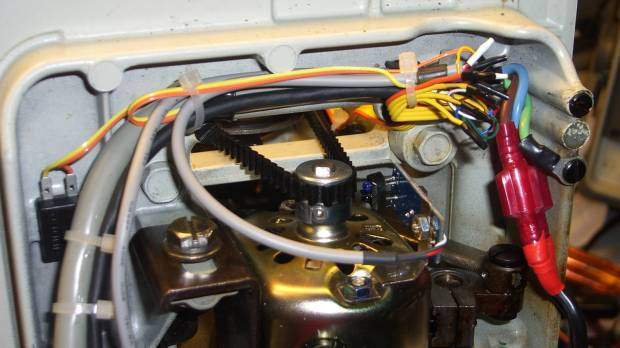
LED Strips and Sensor – cable terminations Unlike the PS/2 connector for the foot pedal, mounting the DB9 “serial” connector required some bashing:
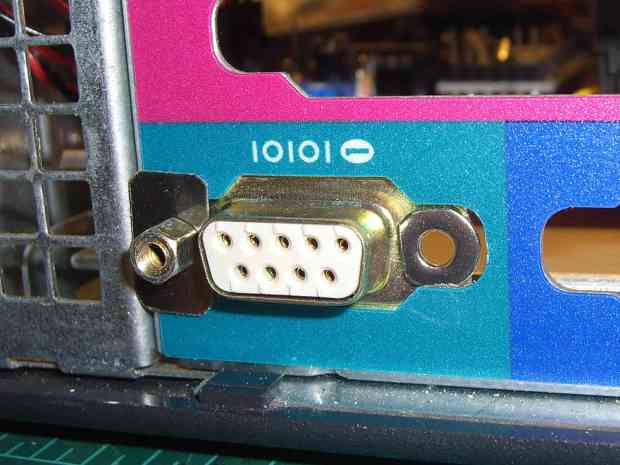
LED and Sensor DB9 – mounting A pair of 4-40 washers, filed to fit inside the chassis cutout and away from the shell, keep the connector from rotating / sliding; the dimensions aren’t conducive to a 3D printed widget. The flat metal strips hold the connector in place, with the mounting screws threaded into 4-40 nuts behind the connector.
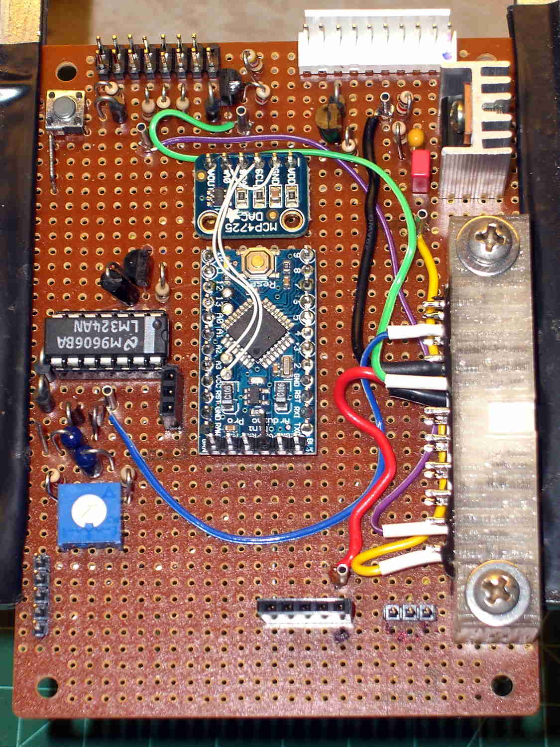
The top row of pins goes to a header (a bit fuzzy, near the bottom of the image) on the Low Voltage Interface board, where the sensor inputs go directly to the Arduino Pro Mini and the power connections to the ATX connector:
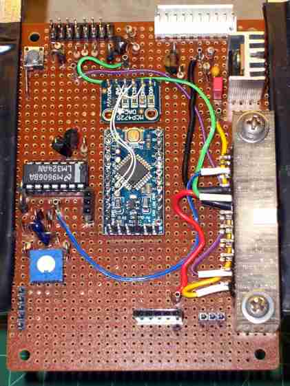
Low Voltage Interface Board – top view The LED power connections on the bottom row go to pins on an ATX wiring harness that used to send juice to the various disk drives.
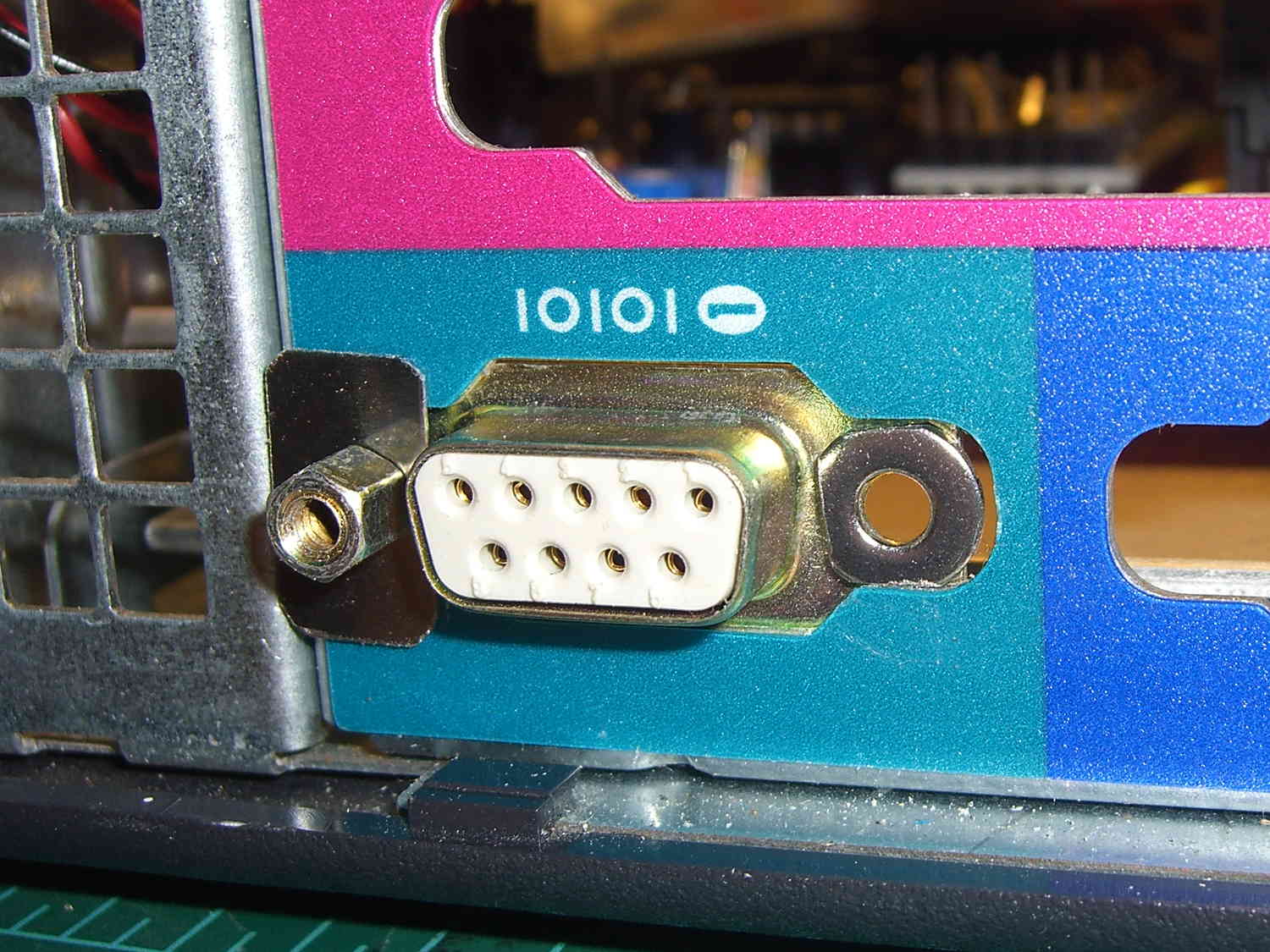
I’m not real happy with that lashup, but … more pondering is in order. I suspect I’ll need a few more conductors for other things on the sewing machine, so a larger cable may terminate at a DB25 connector in the cutout just above this one.

-
Subscribe
Subscribed
Have a WordPress.com account? Log in now.

