-
NTC 2.5 Power Thermistor Characteristics
From a surplus batch, with no provenance, measuring the resistance with current increasing (upper = squares) and then decreasing (lower = diamonds):
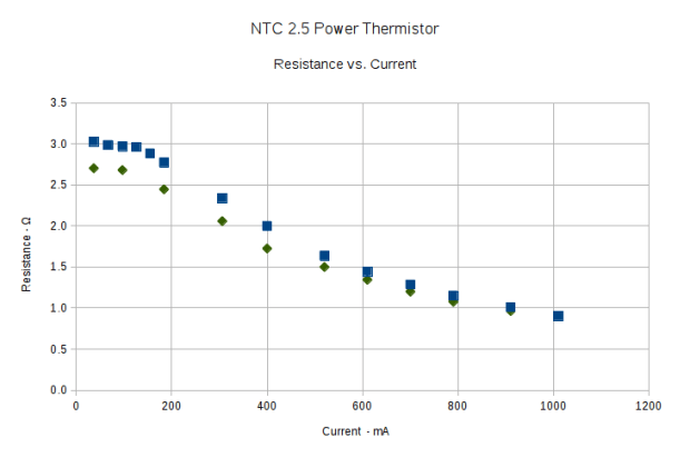
NTC 2.5 Resistance vs Current The resistance at a given current need not lie between those bounds, because it depends strongly on the thermistor’s temperature (duh), which depends on heat loss to the surroundings.
With that in mind, 1 or 2 Ω looks like the right ballpark for these gadgets. Figure around half a watt each at 600 mA; string three in series to get 9 Ω during a cold start and 3 Ω for warm starts. It’s not clear that would solve the transistor killing spike, but it’s a thought.
Compared to the SCK055 NTC thermistor, they have about the same resistance at the same current, despite starting at half the initial cold resistance. I think that’s because they’re somewhat larger and thus run cooler at a given current.
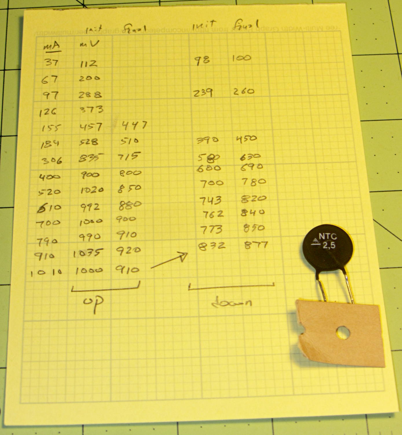
The original data and a portrait of the thermistor:
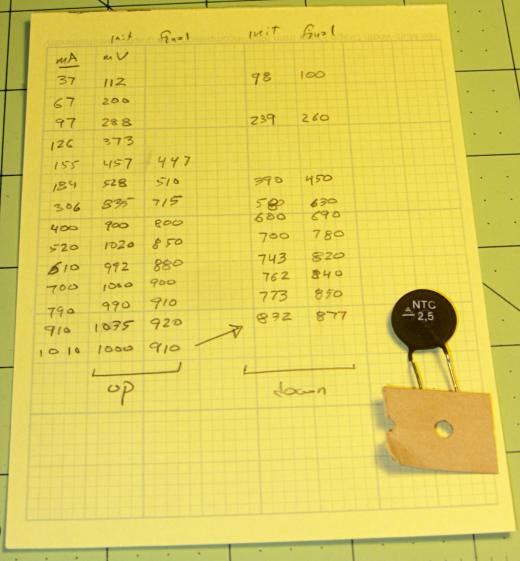
NTC 2.5 Power Thermistor – measurements Anybody recognize the logo? The symbol in the striped triangle is
S+M, if that helps.It’s from TDK/EPCOS: datasheets.

-
Subscribe
Subscribed
Have a WordPress.com account? Log in now.

