-
Adafruit TFT Shield: Firmware Heartbeat Spot
Being that type of guy, I want a visible indication that the firmware continues trudging around the Main Loop. The standard Arduino LED works fine for that (unless you’re using hardware SPI), but the Adafruit 2.8 inch Touch-screen TFT LCD shield covers the entire Arduino board, so I can’t see the glowing chip.
Given a few spare pixels and the Adafruit GFX library, slap a mood light in the corner:
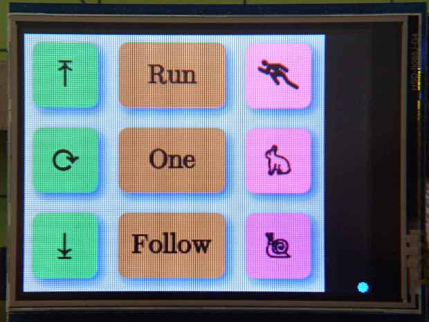
Adafruit TFT – heartbeat spot The library defines the RGB color as a 16 bit
word, so this code produces a dot that changes color every half second around theloop()function:#define PIN_HEARTBEAT 13 unsigned long MillisThen,MillisNow; #define UPDATEMS 500 ... snippage ... void loop() { MillisNow = millis(); ... snippage ... if ((MillisNow - MillisThen) > UPDATEMS) { TogglePin(PIN_HEARTBEAT); tft.fillCircle(315,235,4,(word)MillisNow); // colorful LCD heartbeat MillisThen = MillisNow; } }millis()produces an obvious counting sequence of colors. If that matters, you userandom(0x10000).A square might be slightly faster than a circle. If that matters, you need an actual measurement in place of an opinion.
Not much, but it makes me happy…
There’s an obvious extension for decimal values: five adjacent spots in the resistor color code show you an unsigned number. Use dark gray for black to prevent it from getting lost; light gray and white would be fine. Prefix it with a weird color spot for the negative sign, should you need such a thing.
Hexadecimal values present a challenge. That’s insufficient justification to bring back octal notation.
In this day and age, color-coded numeric readouts should be patentable, as casual searching didn’t turn up anything similar. You saw it here first… [grin]
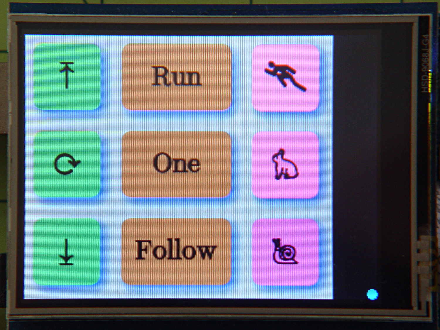
Now that I think about it, a set of tiny buttons that control various modes might be in order.
-
Subscribe
Subscribed
Have a WordPress.com account? Log in now.

