-
Random LED Dots: Hardware Layout
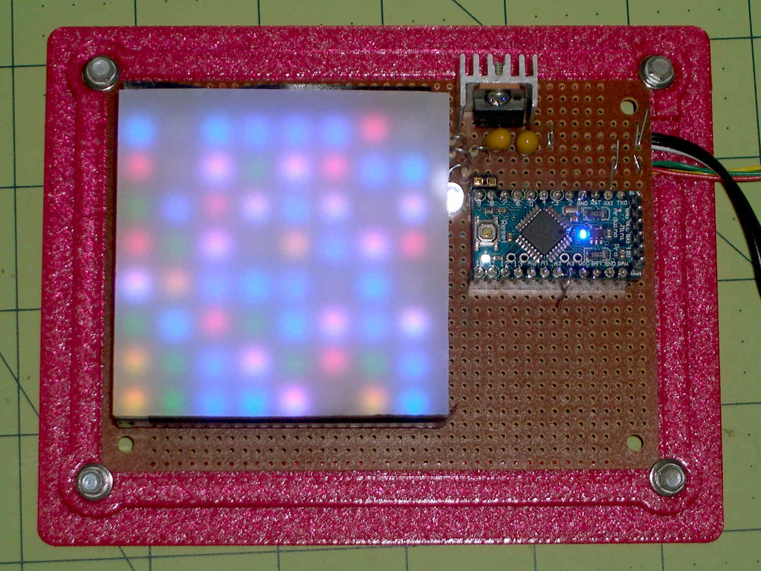
Quite some time ago, Sophi gave me a common-anode RGB LED panel and told me to make something of it. In a spate of desk-clearing, I hammered out a quick-and-dirty multiplexed display from found materials: 2N2907 transistors as row source drivers and 74HC595 shift registers abused as column sink drivers, plus the obligatory Arduino Pro Mini and 3D printed holder:

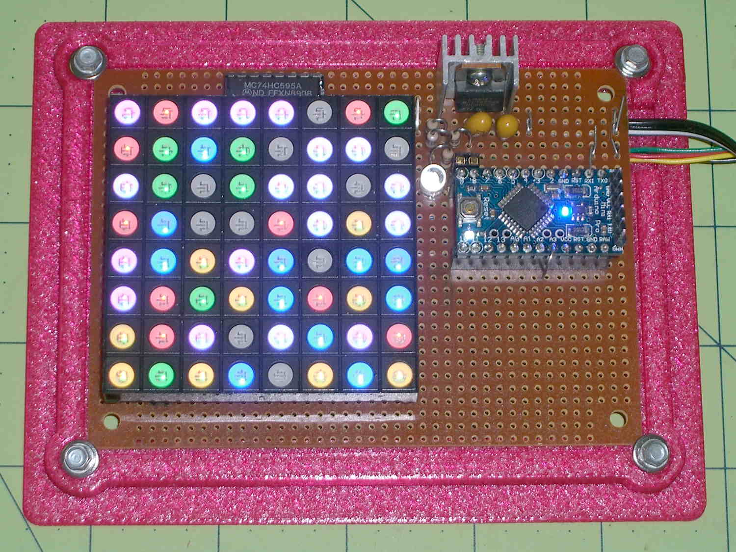
Random LED Dots – circuit board A sheet of milk-white acrylic diffuses the glittery LED dots into pastel disks. I think it might look better without the diffuser; it certainly has a harder-edged tech look:
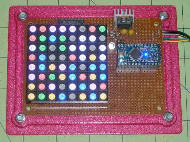
Random LED Dots – overview – no diffuser A neutral-density filter would boost the contrast without hiding any of the details.
It obviously needs an enclosure, but, around here, that’s in the nature of fine tuning.
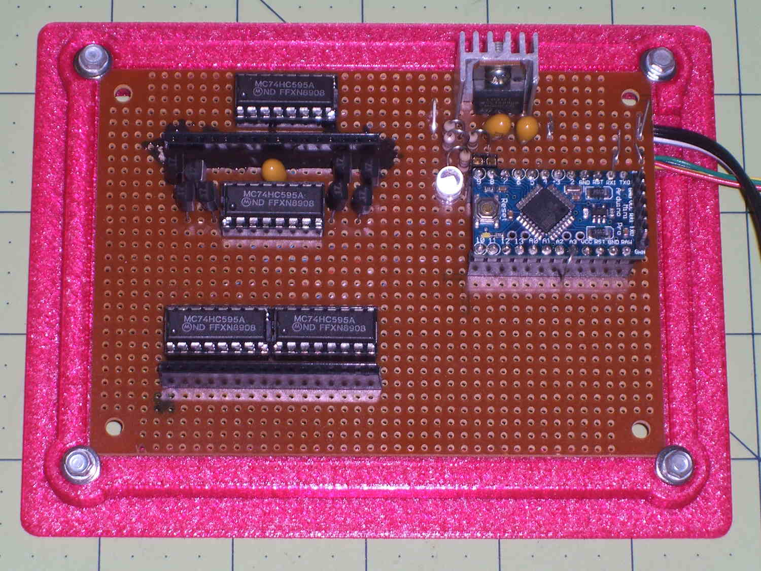
The transistors and shift registers cower under the panel:
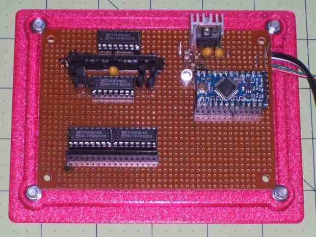
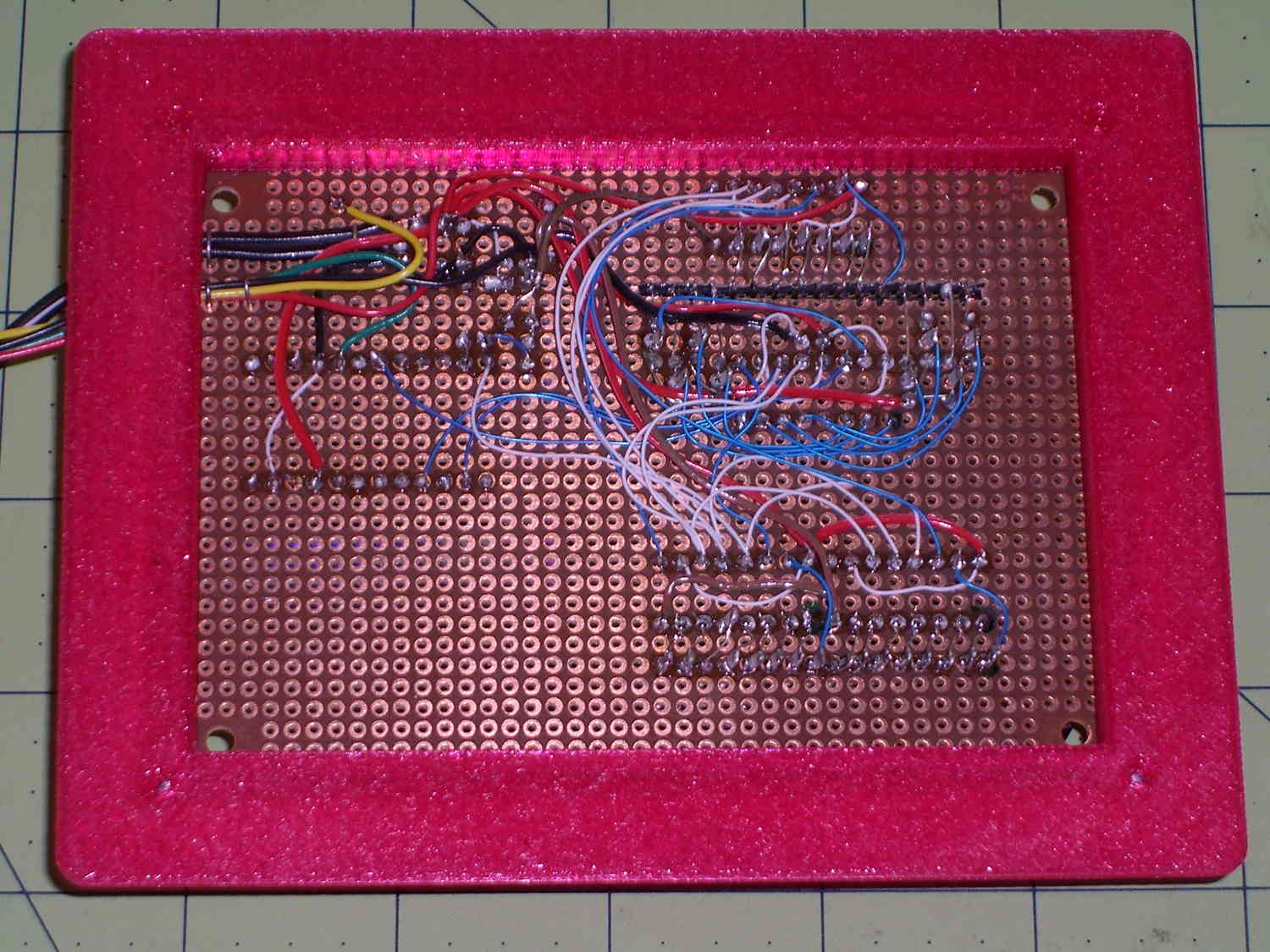
Random LED Dots – circuit layout – top The bottom view exposes the hand wiring, plus the slot required to adapt the LED panel’s non-100-mil layout to the protoboard’s holes. I chopped out the slot with a Dremel saw, attached socket strips to the panel, and epoxied the floating strip in place:
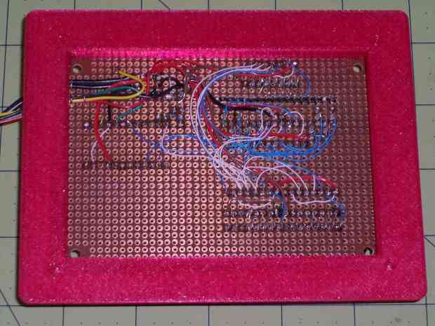
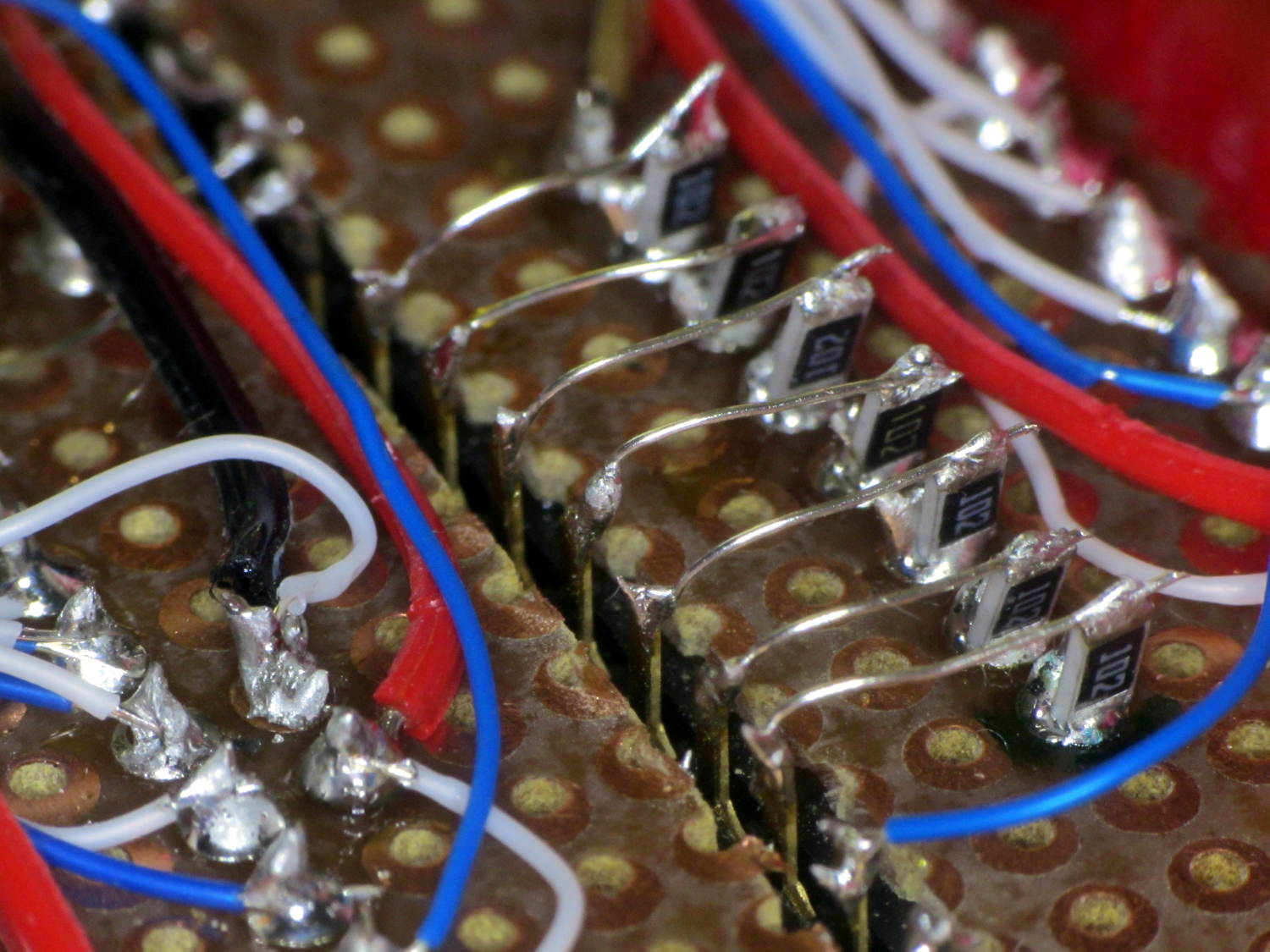
Random LED Dots – circuit layout – bottom The prospect of wiring 32 discrete resistors filled me with dread, so I just tombstoned SMD resistors onto the protoboard solder blobs:
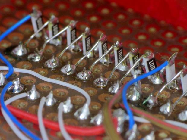
Random LED Dots – circuit layout – RB SMD resistors The slot required slightly longer bridge wires:
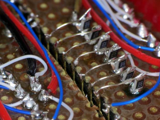
Random LED Dots – circuit layout – G SMD resistors The layout, such as it is, made those short, direct wires possible. A PCB with SMD chips would be even better.
More on the circuitry tomorrow…

-
Subscribe
Subscribed
Have a WordPress.com account? Log in now.

