-
Mini-Lathe: Cover Screw Knobs and Change Gear Protector
About the third time I removed the mini-lathe’s change gear cover by deploying a 4 mm hex wrench on its pair of looong socket head cap screws, I realized that finger-friendly knobs were in order:

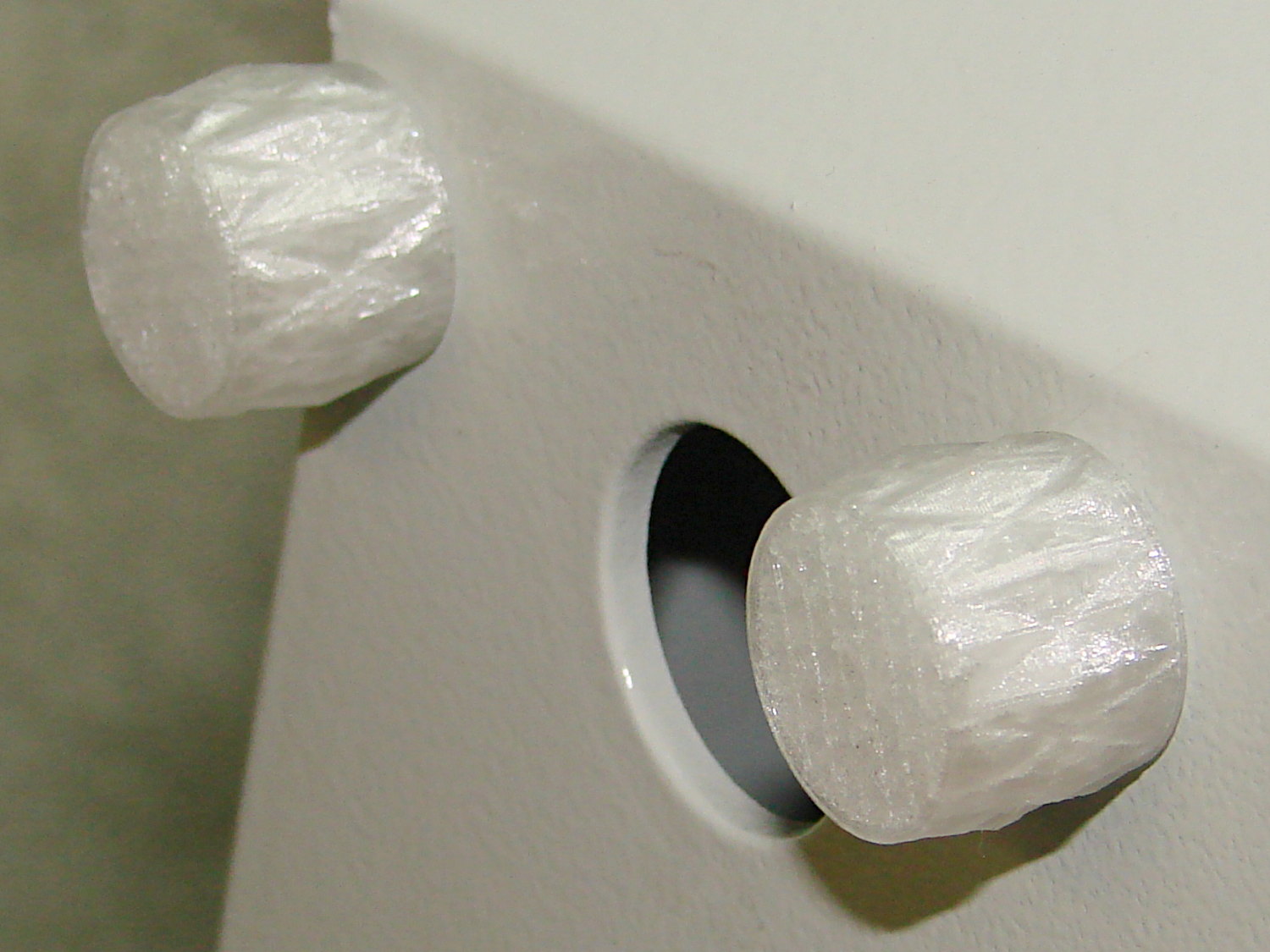
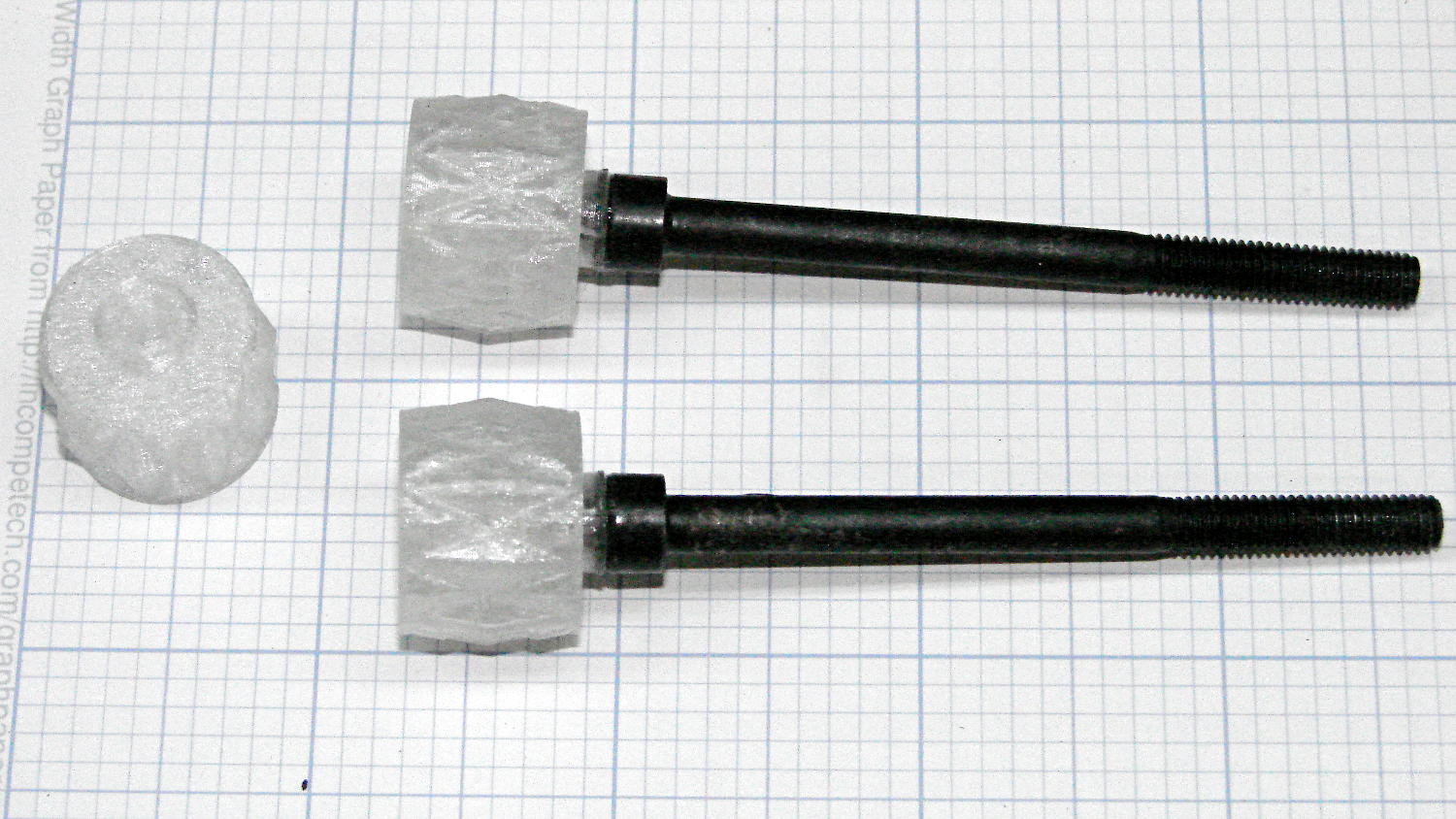
LMS Mini-lathe cover screw knobs – installed A completely invisible length of 4 mm hex key (sliced off with the new miter saw) runs through the middle of the knob into the screw, with a dollop of clear epoxy holding everything together:
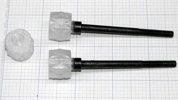
LMS Mini-lathe cover screw knobs – epoxied The 2 mm cylindrical section matches the screw head, compensates for the 1.5 mm recess, and positions the knobs slightly away from the cover:
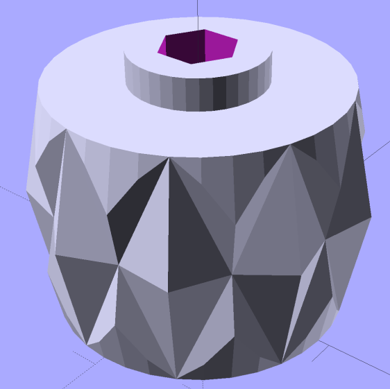
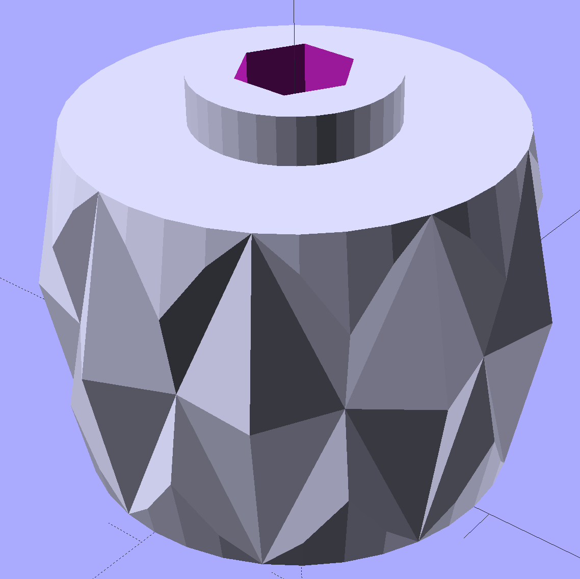
LMS Mini-lathe cover screw knob – solid model They obviously descend from the Sherline tommy bar handles.
I built three of ’em at a time to get a spare to show off and to let each one cool down before the next layer arrives on top:
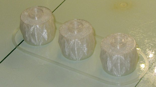
LMS Mini-lathe cover screw knobs – on platform The top and bottom surfaces have Octagram Spiral infill that came out nicely, although it’s pretty much wasted in this application:
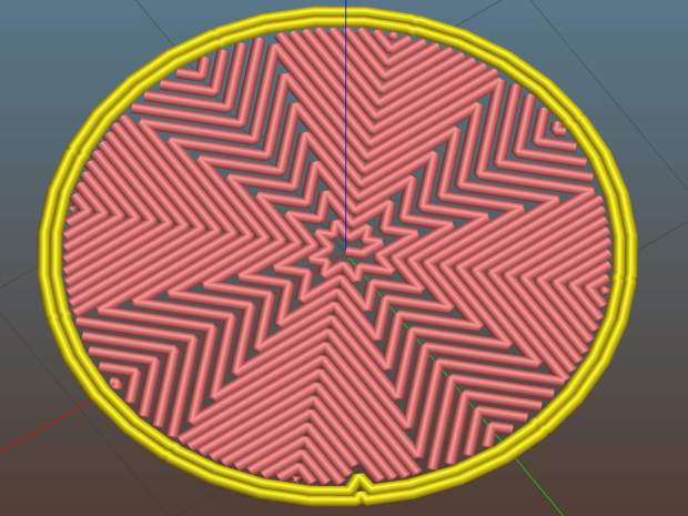
LMS Mini-lathe cover screw knob – Slic3r first layer I have no explanation for that single dent in the perimeter.
The cover hangs from those two screws, which makes it awkward to line up, so I built a shim to support the cover in the proper position:
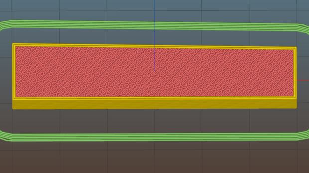
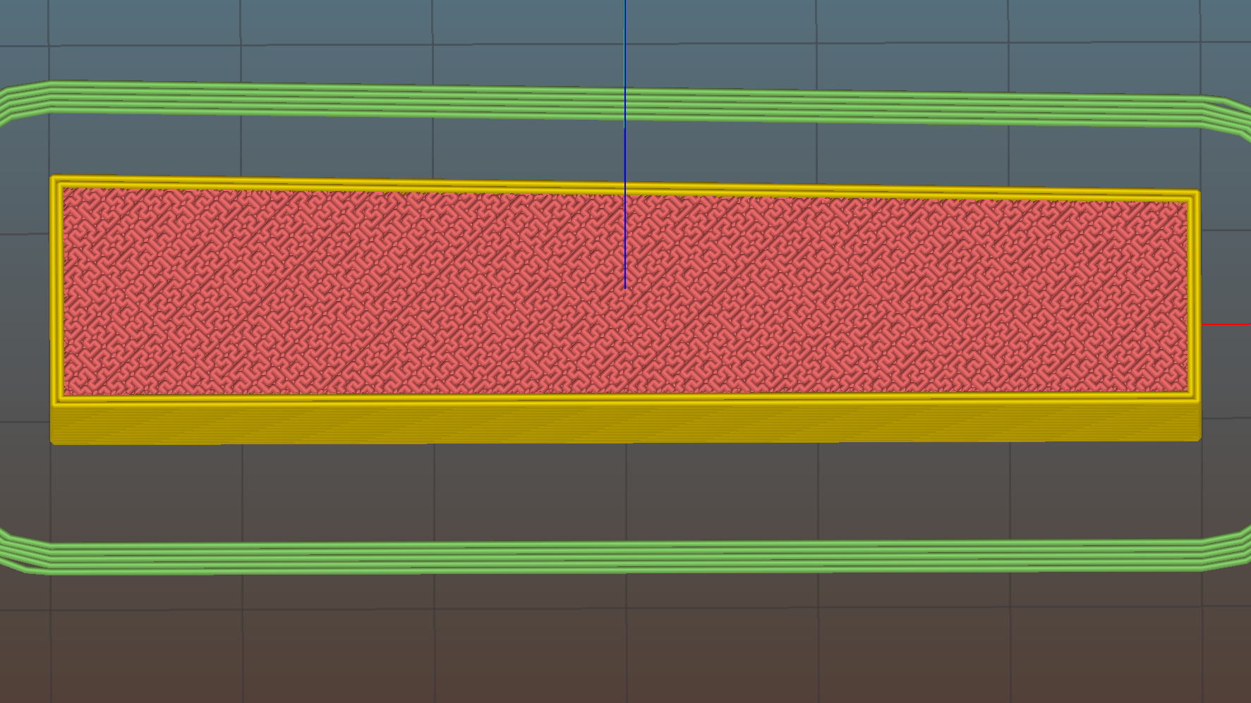
LMS Mini-lathe cover support shim – Slic3r preview Nope, it’s not quite rectangular, as the change gear plate isn’t mounted quite square on the headstock:
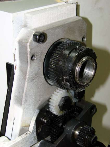
LMS Mini-lathe – cover alignment block I decided
whenif that plate eventually gets moved / adjusted / corrected, I’ll just build a new shim and move on. A length of double-sticky tape holds it onto the headstock.Mounting the cover now requires only two hands: plunk it atop the shim, press it to the right so the angled side settles in place, insert screws, and it’s done.
A short article by Samuel Will (Home Shop Machinist 35.3 May 2016) pointed out that any chips entering the spindle bore will eventually fall out directly into the plastic change gears and destroy them. He epoxied a length of PVC pipe inside the cover to guide the swarf outside, but I figured a tidier solution would be in order:
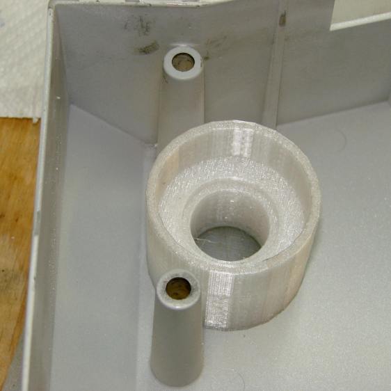
LMS Mini-lathe – change gear shield The solid model looks just like that:
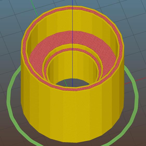
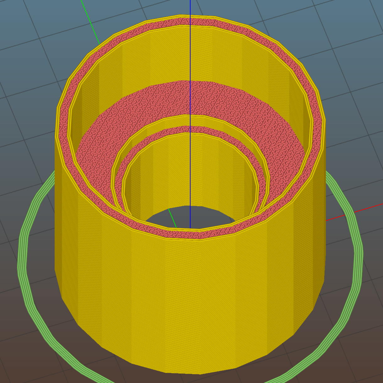
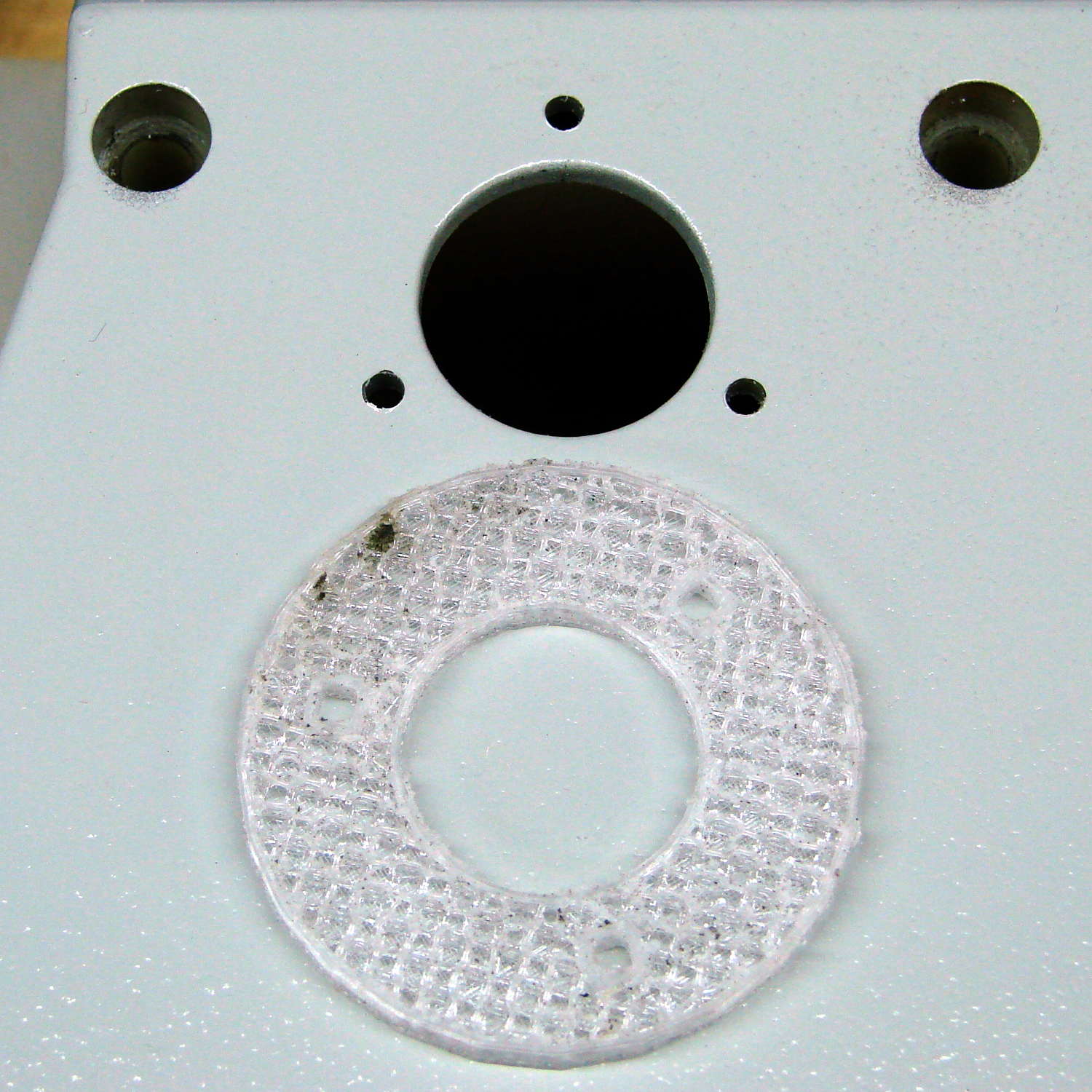
LMS Mini-lathe cover shaft shield – Slic3r preview The backside of the shield has three M3 brass inserts pressed in place. I marked the holes on the cover by the simple expedient of bandsawing the base of the prototype shield (which I needed for a trial fit), lining it up with the spindle hole, and tracing the screw holes (which aren’t yet big enough for the inserts):
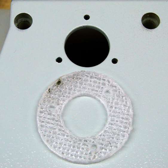
LMS mini-lathe – cover hole template Yeah, that’s burned PETG snot around 10 o’clock on the shield. You could print a separate template if you prefer.
The various diameters and lengths come directly from my lathe and probably won’t be quite right for yours; there’s a millimeter or two of clearance in all directions that might not be sufficient.
Don’t expect the cover hole to line up with the spindle bore:
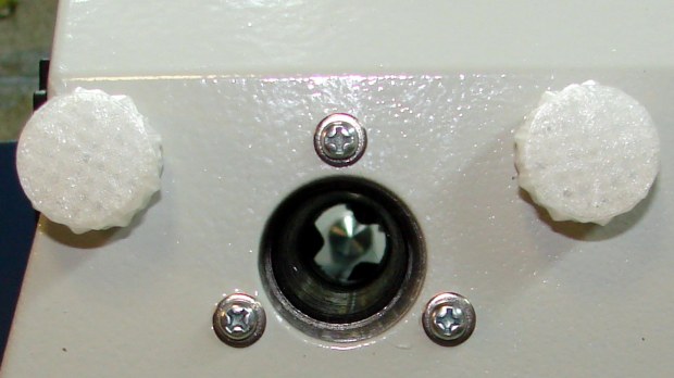
LMS mini-lathe – view through cover and spindle I should build an offset into the shield that jogs the holes in whatever direction makes the answer come out right, but that’s in the nature of fine tuning; those holes got filed slightly egg-shaped to ease the shield a bit to the right and it’s all good.
Heck, having the spindle line up pretty closely with the tailstock seems like enough of a bonus for one day.
The OpenSCAD source code as a GitHub Gist:
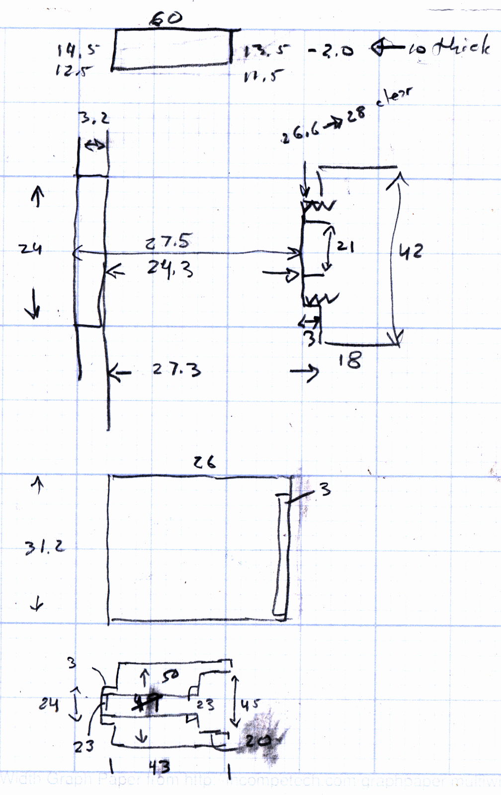
This file contains hidden or bidirectional Unicode text that may be interpreted or compiled differently than what appears below. To review, open the file in an editor that reveals hidden Unicode characters. Learn more about bidirectional Unicode characters// Tweakage for LMS Mini-Lathe cover // Ed Nisley – KE4ZNU – June 2016 Layout = "Shaft"; // Knob Shim Shaft use <knurledFinishLib_v2.scad> //- Extrusion parameters must match reality! // Print with 2 shells and 3 solid layers ThreadThick = 0.20; ThreadWidth = 0.40; HoleWindage = 0.3; // extra clearance to improve hex socket fit Protrusion = 0.1; // make holes end cleanly inch = 25.4; //———————- // Dimensions //- Knobs for cover screws HeadDia = 8.5; // un-knurled section diameter HeadRecess = 2.0; // … length inside cover surface + some clearance SocketDia = 4.0; // hex key size SocketDepth = 10.0; KnurlLen = 15.0; // length of knurled section KnurlDia = 20.0; // … diameter at midline of knurl diamonds KnurlDPNom = 12; // Nominal diametral pitch = (# diamonds) / (OD inches) DiamondDepth = 1.5; // … depth of diamonds DiamondAspect = 4; // length to width ratio KnurlID = KnurlDia – DiamondDepth; // dia at bottom of knurl NumDiamonds = ceil(KnurlDPNom * KnurlID / inch); echo(str("Num diamonds: ",NumDiamonds)); NumSides = 4*NumDiamonds; // 4 facets per diamond KnurlDP = NumDiamonds / (KnurlID / inch); // actual DP echo(str("DP Nom: ",KnurlDPNom," actual: ",KnurlDP)); DiamondWidth = (KnurlID * PI) / NumDiamonds; DiamondLenNom = DiamondAspect * DiamondWidth; // nominal diamond length DiamondLength = KnurlLen / round(KnurlLen/DiamondLenNom); // … actual TaperLength = 0*DiamondLength; //- Shim to support cover CoverTopThick = 2.0; ShimThick = 10.0; ShimCornerRadius = 2.0; ShimPoints = [[0,0],[60,0],[60,(13.5 – CoverTopThick)],[0,(14.5 – CoverTopThick)]]; //- Shaft extension to keep crap out of the change gear train ID = 0; OD = 1; LENGTH = 2; Shaft = [24.0,30.0,41.0]; // ID=through, OD=thread OD, Length = cover to nut seat ShaftThreadLength = 3.0; ShaftSides = 6*4; ShaftNut = [45,50,16]; // recess around shaft nut, OD = outside of cover Insert = [3.5,5.0,8.0]; // 3 mm threaded insert NumCoverHoles = 3; CoverHole = [Insert[OD],35.0,12.0]; // ID = insert, OD = BCD, LENGTH = screw hole depth ShaftPoints = [ [Shaft[ID]/2,0], [ShaftNut[OD]/2,0], [ShaftNut[OD]/2,Shaft[LENGTH]], [ShaftNut[ID]/2,Shaft[LENGTH]], [ShaftNut[ID]/2,Shaft[LENGTH] – ShaftNut[LENGTH]], [Shaft[OD]/2, Shaft[LENGTH] – ShaftNut[LENGTH]], [Shaft[OD]/2, Shaft[LENGTH] – ShaftNut[LENGTH] – ShaftThreadLength], [Shaft[ID]/2, Shaft[LENGTH] – ShaftNut[LENGTH] – ShaftThreadLength], ]; //———————- // Useful routines module PolyCyl(Dia,Height,ForceSides=0) { // based on nophead's polyholes Sides = (ForceSides != 0) ? ForceSides : (ceil(Dia) + 2); FixDia = Dia / cos(180/Sides); cylinder(r=(FixDia + HoleWindage)/2, h=Height, $fn=Sides); } //- Build things if (Layout == "Knob") difference() { union() { render(convexity=10) translate([0,0,TaperLength]) // knurled cylinder knurl(k_cyl_hg=KnurlLen, k_cyl_od=KnurlDia, knurl_wd=DiamondWidth, knurl_hg=DiamondLength, knurl_dp=DiamondDepth, e_smooth=DiamondLength/2); color("Orange") // lower tapered cap cylinder(r1=HeadDia/2, r2=(KnurlDia – DiamondDepth)/2, h=(TaperLength + Protrusion), $fn=NumSides); color("Orange") // upper tapered cap translate([0,0,(TaperLength + KnurlLen – Protrusion)]) cylinder(r2=HeadDia/2, r1=(KnurlDia – DiamondDepth)/2, h=(TaperLength + Protrusion), $fn=NumSides); color("Moccasin") // cylindrical extension translate([0,0,(2*TaperLength + KnurlLen – Protrusion)]) cylinder(r=HeadDia/2,h=(HeadRecess + Protrusion),$fn=NumSides); } translate([0,0,(2*TaperLength + KnurlLen + HeadRecess – SocketDepth + Protrusion)]) PolyCyl(SocketDia,(SocketDepth + Protrusion),6); // hex key socket } if (Layout == "Shim") linear_extrude(height=(ShimThick)) // overall flange around edges polygon(points=ShimPoints); if (Layout == "Shaft") difference() { rotate_extrude($fn=ShaftSides,convexity=5) polygon(points=ShaftPoints); for (i=[0:NumCoverHoles-1]) rotate(i*360/NumCoverHoles) translate([CoverHole[OD]/2,0,-Protrusion]) rotate(180/8) PolyCyl(Insert[OD],15,8); } The original doodle with more-or-less actual dimensions and clearances and suchlike:
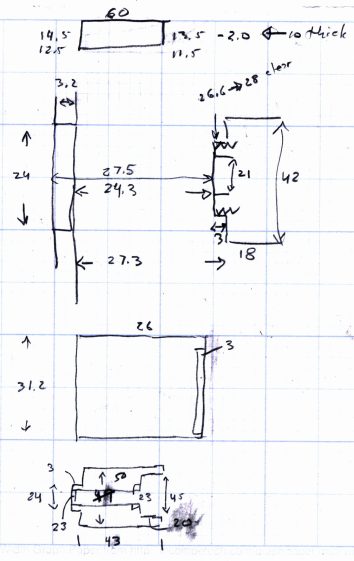
Cover to Shaft spacing doodles





-
Subscribe
Subscribed
Have a WordPress.com account? Log in now.

