-
Miniblind Bottom Rail Caps
A few days after installing the replacement cord caps, I bumped the bottom rail of the miniblind while opening the window and had one endcap disintegrate; apparently window hardware isn’t hardened against prolonged UV exposure. Who knew?
Fortunately, I can fix that:
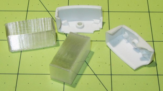
Miniblind bottom rail caps Making the walls three threads wide provides enough room for a single solid infill thread:
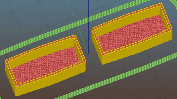
Miniblind Endcaps – Slic3r Preview The exterior shape comes from a hull wrapped around six circles: four to define the corner radius and a pair that bump the center out by the calculated chord height. The interior shape comes from a pair of chord-radius polygonal circles (they only have three facets across the length of the inside wall) that fit the bottom rail almost perfectly.
As always, natural PETG has a crystalline, slightly transparent, appearance:
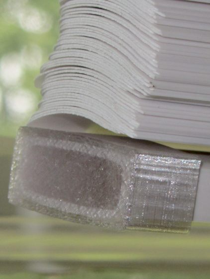
Miniblind bottom rail cap installed I should spring for some opaque white filament, but that way lies madness; I might start caring what these things look like.
You can buy entire miniblinds for a few bucks a pop, but the last time we did that, they were different than the ones we had before. That wouldn’t matter if the standard miniblind mounting brackets fit our 1955 Anderson windows, but noooo they don’t: the custom adapters I machined for the first miniblind brackets, of course, didn’t fit the new miniblinds.
Now I can just snap the replacement endcaps (and cord pulls) in place, declare victory, and move on.
The OpenSCAD source code as a GitHub Gist:
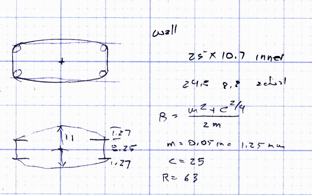
This file contains hidden or bidirectional Unicode text that may be interpreted or compiled differently than what appears below. To review, open the file in an editor that reveals hidden Unicode characters. Learn more about bidirectional Unicode characters// Cap for miniblind cord and bottom rail endcaps // Ed Nisley KE4ZNU – September 2016 Layout = "BaseEndCap"; // CordCap BaseEndCap //- Extrusion parameters – must match reality! ThreadThick = 0.25; ThreadWidth = 0.40; Protrusion = 0.1; HoleWindage = 0.2; //—— // Dimensions OD1 = 0; OD2 = 1; LENGTH = 2; //———————- //- Build it if (Layout == "CordCap") { Cap = [9.0,16.0,25.0]; Cord = [2.5,7.0,Cap[LENGTH] – 5]; NumSides = 8; difference() { hull() { // overall shape translate([0,0,Cap[LENGTH] – Cap[OD1]/2]) sphere(d=Cap[OD1],$fn=NumSides); translate([0,0,0.5*Cap[OD2]/2]) sphere(d=Cap[OD2],$fn=2*NumSides); // round the bottom just a bit } translate([0,0,-Cap[LENGTH]/2]) // trim bottom cube([2*Cap[OD2],2*Cap[OD2],Cap[LENGTH]],center=true); translate([0,0,Cap[LENGTH] + 0.8*Cap[OD1]]) // trim top (arbitrarily) cube([2*Cap[OD1],2*Cap[OD1],2*Cap[OD1]],center=true); translate([0,0,-Protrusion]) cylinder(d=Cord[OD1],h=(Cap[LENGTH] + 2*Protrusion),$fn=NumSides); translate([0,0,-Protrusion]) cylinder(d1=Cord[OD2],d2=Cord[OD1],h=(Cord[LENGTH] + Protrusion),$fn=NumSides); } } if (Layout == "BaseEndCap") { Base = [25.2,9.0,12.2]; // base outside dimensions Edge = 8.0; // size of sqare ends CornerRadius = 0.75; Wall = 3; // wall thickness in threads ChordHeight = (Base[1] – Edge) / 2; ChordRadius = (pow(ChordHeight,2) + pow(Base[0],2)/4) / (2*ChordHeight); NumSides = 4*4; echo(str("Chord height: ",ChordHeight," radius: ",ChordRadius)); difference() { linear_extrude(height=Base[2],convexity=2) { hull() { for (i=[-1,1], j=[-1,1]) translate([i*(Base[0]/2 – CornerRadius + Wall*ThreadWidth),j*(Base[1]/2 – CornerRadius + Wall*ThreadWidth)]) circle(r=CornerRadius,$fn=4*4,center=true); for (j=[-1,1]) translate([0,j*(ChordHeight + Base[1]/2 – CornerRadius + Wall*ThreadWidth)]) rotate(180/(2*4)) circle(r=CornerRadius,$fn=2*4,center=true); } } translate([0,0,3*ThreadThick]) linear_extrude(height=Base[2],convexity=2) intersection() { intersection_for (j=[-1,1]) translate([0,j*(ChordHeight + Base[1]/2 – ChordRadius)]) circle(r=ChordRadius,$fn=32*4,center=true); square([Base[0],2*Base[1]],center=true); } } } The original doodle with some dimensions that didn’t withstand careful measurements:
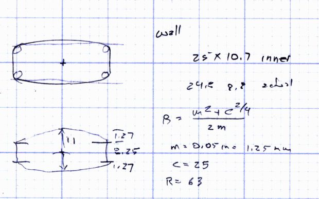
Miniblind Endcap dimension doodle


-
Subscribe
Subscribed
Have a WordPress.com account? Log in now.

