-
Medicare Advantage Mail Merge: FAIL
A postcard arrived last week telling me to call a special number for special deals on Medicare Advantage plans. Being that type of guy, I managed to read the microscopic Fine Print and found this amusing blooper amid the
disclaimersweasel wording: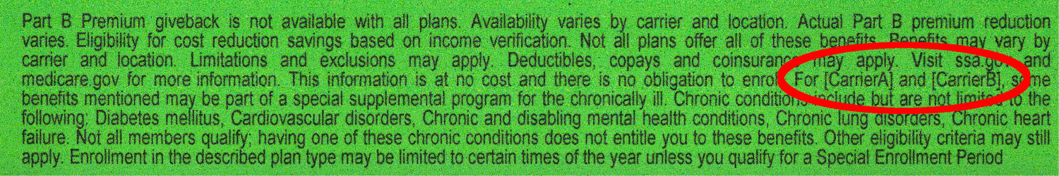
Medicare Advantage mail spam Inserting insurance carrier names should have happened before printing the card, so
[CarrierA]and[CarrierB]are either placeholders or mail-merge variables.Also, you’re seeing the contrast-blown and magnified version of the postcard. The original Fine Print had faint orange ink on light green cardstock: colors having different hues with the same saturation and value to minimize legibility. In general, folks eligible for Medicare Advantage plans have trouble reading Fine Print, so the choice was not accidental.
Not a compelling value proposition, as they say.
-
Subscribe
Subscribed
Already have a WordPress.com account? Log in now.
