-
Tour Easy Daytime Running Light: Ball Clamp Ring
With the flashlight firmly clamped inside its ball, a surrounding clamp ring holds the ball on the mount:
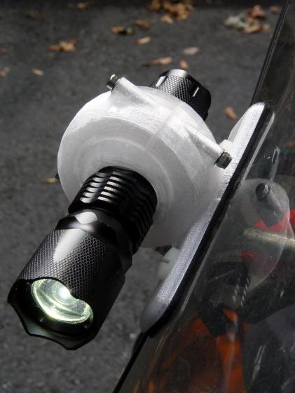
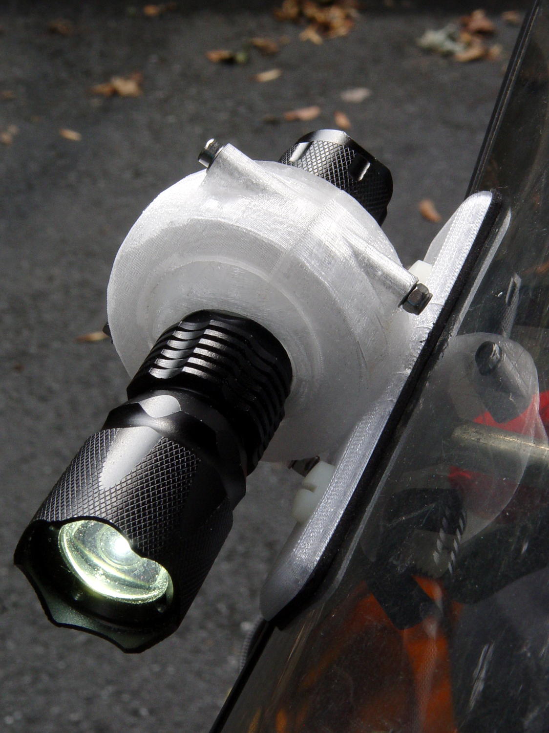
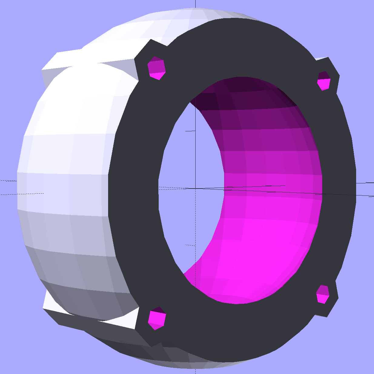
Tour Easy – J5 Tactical V2 – front The solid model chops a sphere to a completely empirical 70% of the inner ball’s length (which, itself, may be truncated to fit the flashlight grip) and glues on a hull containing the M3x50 mm screws:
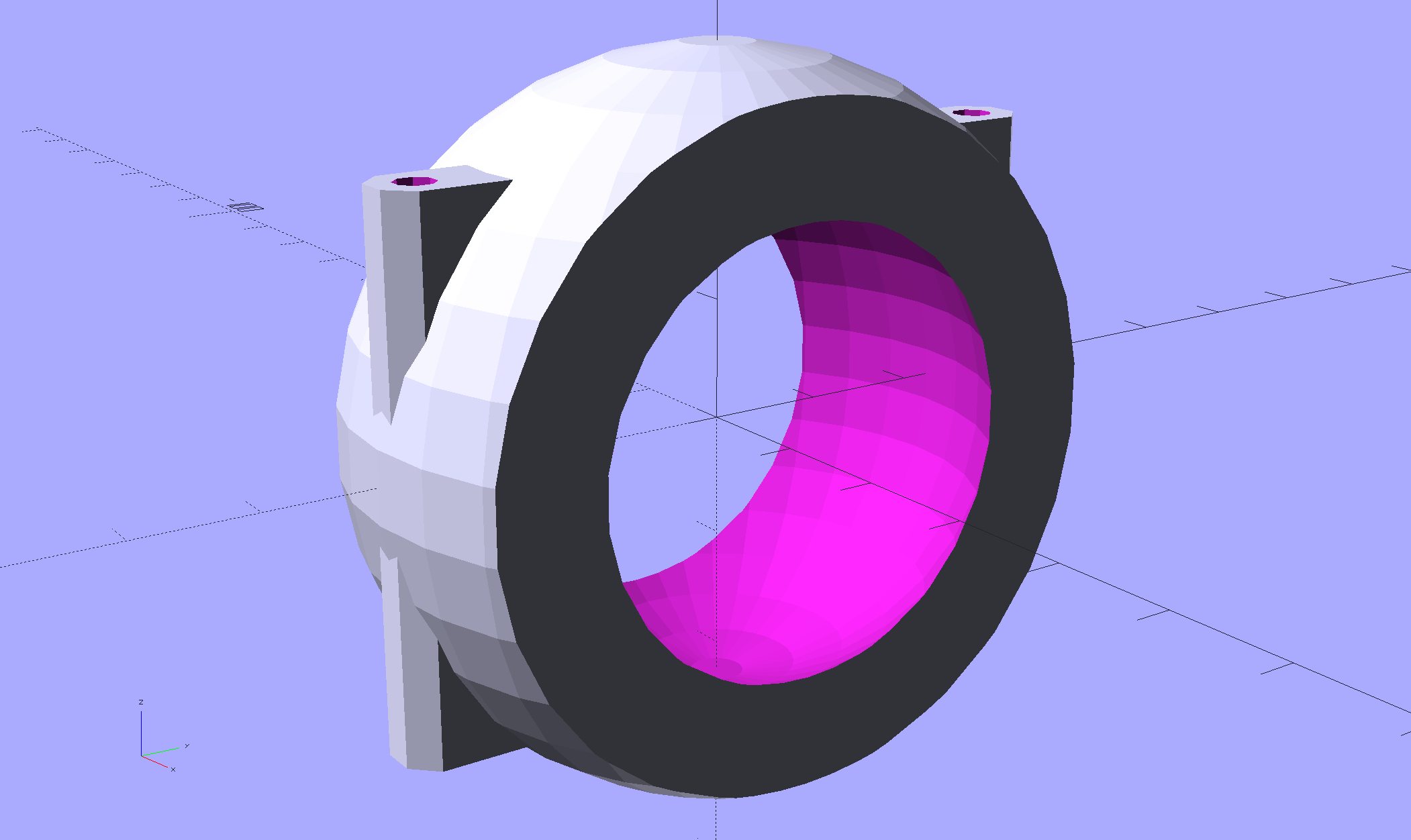
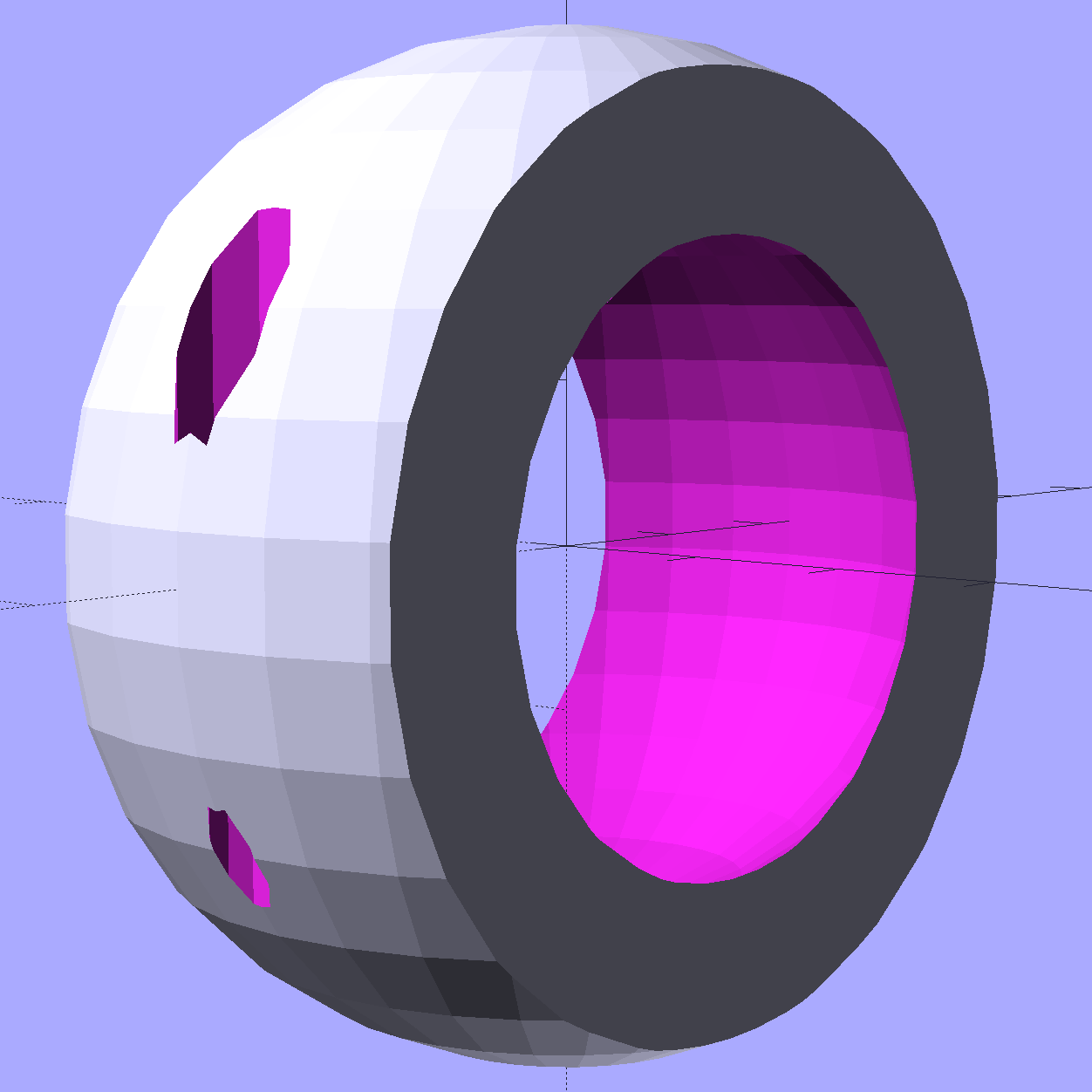
This file contains hidden or bidirectional Unicode text that may be interpreted or compiled differently than what appears below. To review, open the file in an editor that reveals hidden Unicode characters. Learn more about bidirectional Unicode characters//- Clamp around flashlight ball module BallClamp() { BossLength = ClampScrew[LENGTH] – ClampScrewNut[LENGTH] – 2*ClampScrewWasher[LENGTH] – 4*ThreadThick; difference() { union() { intersection() { sphere(d=ClampOD,$fn=NumSides); // exterior ball blamp cube([ClampLength,2*ClampOD,2*ClampOD],center=true); // aiming allowance } for (i=[0]) hull() { for (j=[-1,1]) translate([i*(ClampLength/2 – ClampScrew[OD]),j*ClampScrewOC/2,-BossLength/2]) rotate(180/8) cylinder(d=(ClampScrewWasher[OD] + 2*ThreadWidth),h=BossLength,$fn=8); } } sphere(d=(BallOD + 1*ThreadThick),$fn=NumSides); // interior ball for (i=[0] , j=[-1,1]) { translate([i*(ClampLength/2 – ClampScrew[OD]),j*ClampScrewOC/2,-ClampOD]) // screw clearance rotate(180/8) PolyCyl(ClampScrew[ID],2*ClampOD,8); } } color("Yellow") if (Support) { // ad-hoc supports for top half NumRibs = 6; RibLength = 0.5 * BallOD; RibWidth = 1.9*ThreadWidth; SupportOC = ClampLength / NumRibs; cube([ClampLength,RibLength,4*ThreadThick],center=true); // base plate for adhesion intersection() { sphere(d=BallOD – 0*ThreadWidth); // cut at inner sphere OD cube([ClampLength + 2*ThreadWidth,RibLength,BallOD],center=true); union() { // ribs for E-Z build for (j=[-1,0,1]) translate([0,j*SupportOC,0]) cube([ClampLength,RibWidth,1.0*BallOD],center=true); for (i=[0:NumRibs]) // allow +1 to fill the far end translate([i*SupportOC – ClampLength/2,0,0]) rotate([0,90,0]) cylinder(d=BallOD – 2*ThreadThick, h=RibWidth,$fn=NumSides,center=true); } } } } The complete ring looks about like you’d expect, although it’s never built like this:

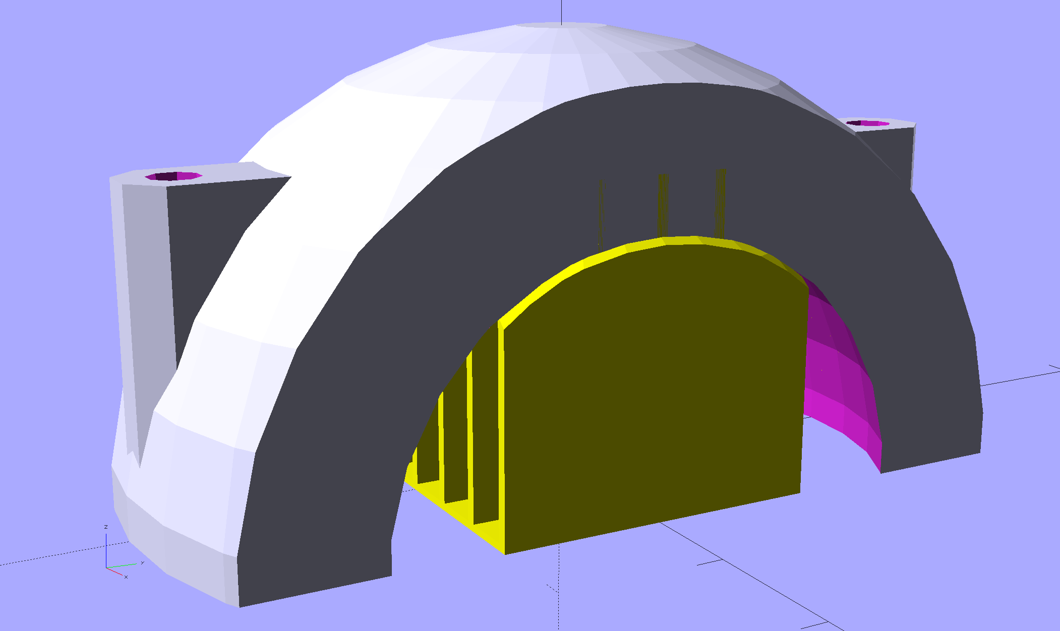
Fairing Flashlight Mount – Clamp – show view – solid model The top half builds as an arch on the platform:

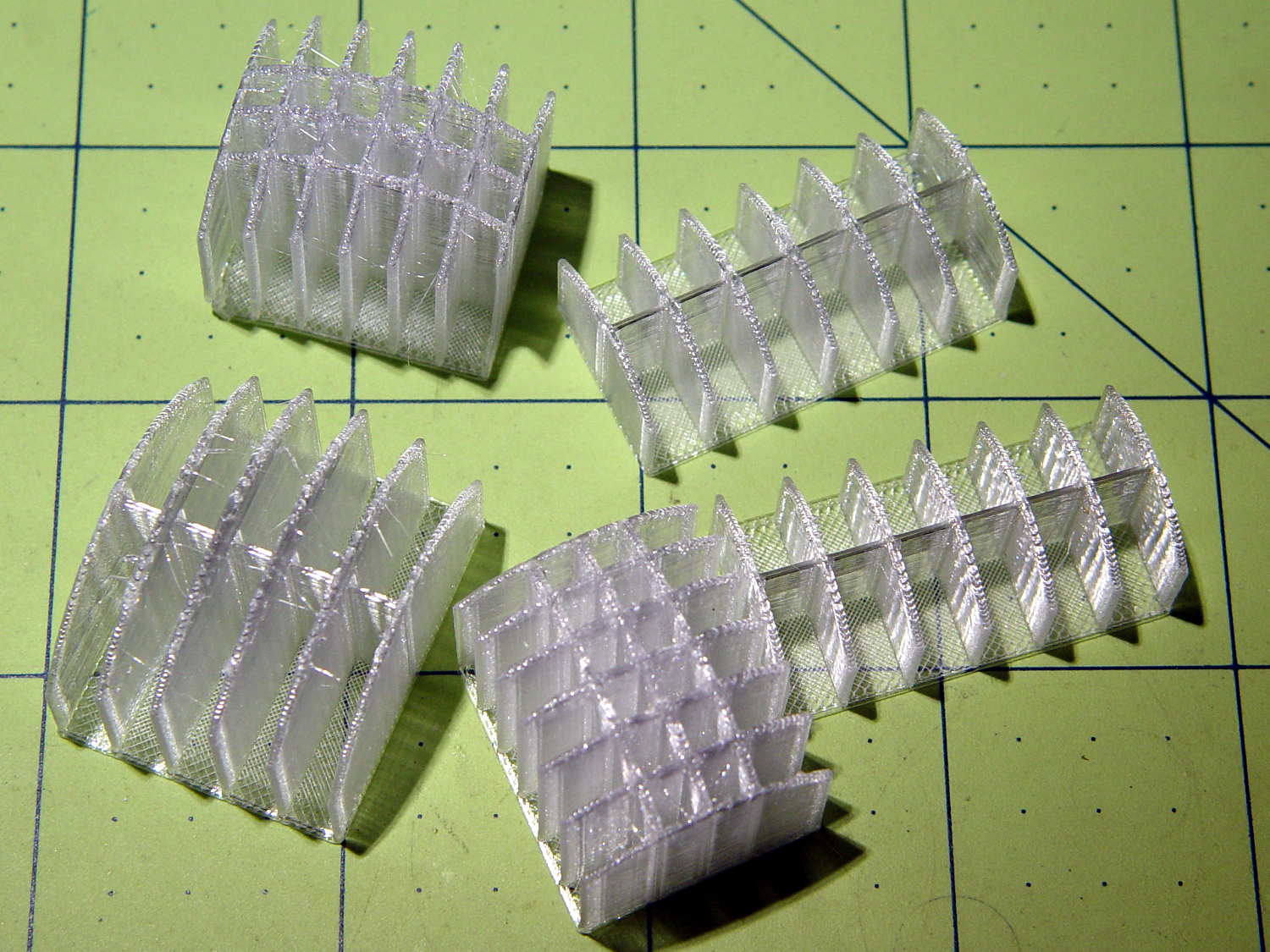
Fairing Flashlight Mount – Clamp – build view – solid model The uppermost layers on the inside of the arch have terrible overhang pulled upward by the cooling plastic, so the builtin support structure hold the layers downward. The preview shows they don’t quite touch, but in actual practice the support bonds to the arch and requires a bit of effort to crack off:

Fairing Flashlight Mount – support structures The ones on the right come from my (failed) attempts to build the ball hemispheres in the obvious orientation. It’s worth noting that my built-in “support” both bonds to the part and breaks off in one piece, quite unlike the pitched battle required to separate Slic3r’s automatic support structures; I think that’s the difference between the minimum feasible and maximum possible support.
Anyhow, the inside of the arch requires only a bit of cleanup with a ball mill before it clamps firmly around the flashlight ball. In the normal orientation, the space over the missing ball cap snuggles into the cleaned-up part of the arch and there’s enough friction on the remaining ball to hold it in place. If it does joggle loose, a wrap of tape should provide enough griptivity.
I started by assuming socket-head cap screws and brass inserts embedded in the clamp ring could provide enough force to hold everything together:

Fairing Flashlight Mount – Clamp – screw inserts – solid model The head recesses into the top opening and the insert sits just below the split line on the XY plane. That turned out to be asking a lot from a pair of 3 mm knurled brass inserts, even with JB Weld in full effect, and I wasn’t at all confident they wouldn’t pop out under duress and fling the flashlight away.
Each screw now compresses the entire boss between a pair of washers and the nyloc nut won’t vibrate loose. The screws also serve to stiffen the clamp ring front-to-back, although I’m not convinced it needs any reinforcement.
I also considered splitting the ring parallel to the front, right down the middle, with screws extending through both halves:

Fairing Flashlight Mount – Clamp – Front Back split – solid model It’d be trivially easy to build the front half face-down on the platform, but the rear would have only half the surface area bonded to the plate against the fairing, which seemed like a Bad Idea. Worse, I couldn’t figure out how to align the rear half on the plate with enough room for the nuts / inserts / whatever and alignment space around the front half.
-
Subscribe
Subscribed
Have a WordPress.com account? Log in now.

