-
MPCNC: USB Camera Mount
The bCNC doc shows a camera mount made from acrylic and aluminum, but the MPCNC tool carrier lacks anywhere to secure such a thing. The camera should be reasonably close to the spindle axis, high enough to clear the work, and stable enough to hold its alignment. There’s a tiny flat spot next to the outer-lower Z-axis bearing supports (along the bottom of the picture), so that’s where it must go:
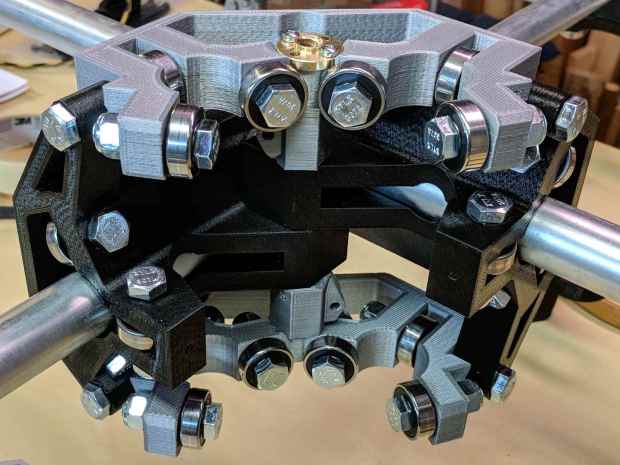
MPCNC – Central Assembly – detail At least for now, anyway.
The USB camera originally mounted on a spring clip, with a 10 mm ball at the end of a 6 mm OD × 6 mm long stalk. Because we live in the future, building a matching ball socket isn’t particularly difficult:
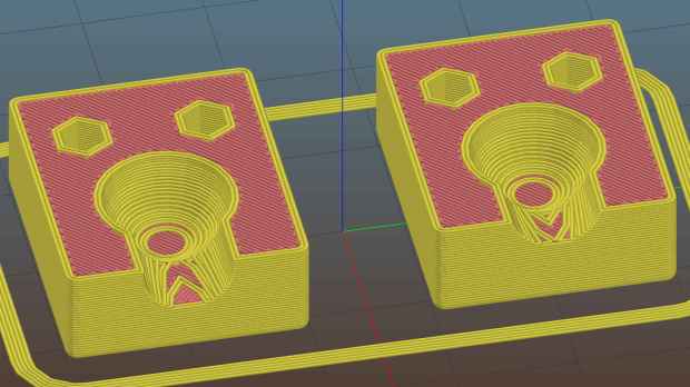
MPCNC – USB Camera mount – Slic3r 3D printing FTW!
The stalk opening slants downward by 5°, because the camera PCB isn’t quite aligned with the stalk and I couldn’t get the first version to aim the lens directly downward.
A pair of brass inserts anchor the two M3 SHCS. The clamping force seems barely adequate to the task, but I’ll wait to see what else I don’t like before complexicating the situation.
A square of Genuine 3M sticky foam tape holds the mount to the MPCNC beside the DeWalt DW660 spindle:
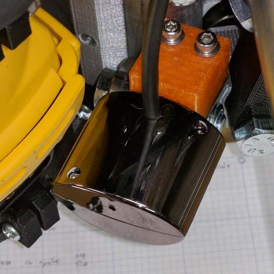
MPCNC USB Camera – installed The MPCNC bearing bracket doesn’t provide much surface area for the foam and it’s a bit more flexy than I’d like, but good practice probably requires verifying the spindle-to-camera offset before trusting the results, so we’ll see how it works.
The initial camera alignment consists of putting a mirror flat on the (pretty much level) platform:
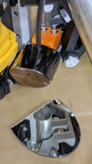
MPCNC USB Camera – mirror alignment Then you adjust the camera so its lens looks squarely at itself in the middle of the image:
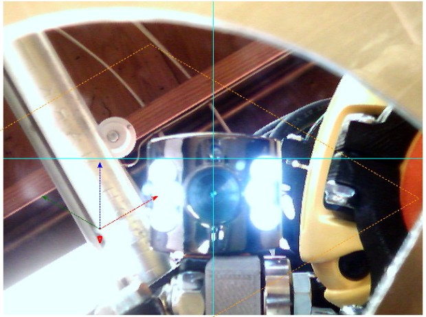
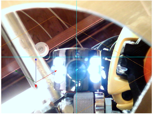
bCNC – Camera – Mirror Alignment – first mount The picture shows the camera aligned left-to-right (because the ball can rotate around the shaft axis), but the first mount didn’t allow the stalk to have enough downward tilt to center the lens image on the horizontal crosshair, thus the -5° tilt appearing in the second version.
With the camera lens centered on its reflection, you know the optical axis is perpendicular to the mirror. Because the mirror is flat on the bench, the optical axis must be perpendicular to the bench, which is parallel to the XY plane. Because we assume the MPCNC Z-axis moves perpendicular to the bench = XY plane, the distance between the spindle axis and the camera axis will remain constant, regardless of the Z-axis position.
Seems workable to me.
The OpenSCAD program as a GitHub Gist:
This file contains hidden or bidirectional Unicode text that may be interpreted or compiled differently than what appears below. To review, open the file in an editor that reveals hidden Unicode characters. Learn more about bidirectional Unicode characters// MPCNC USB Camera Mount // Ed Nisley KE4ZNU – 2018-02-16 Layout = "Build"; // Build, Show, Mount /* [Extrusion] */ ThreadThick = 0.25; // [0.20, 0.25] ThreadWidth = 0.40; // [0.40] /* [Hidden] */ Protrusion = 0.1; // [0.01, 0.1] HoleWindage = 0.2; inch = 25.4; function IntegerMultiple(Size,Unit) = Unit * ceil(Size / Unit); ID = 0; OD = 1; LENGTH = 2; //- Adjust hole diameter to make the size come out right module PolyCyl(Dia,Height,ForceSides=0) { // based on nophead's polyholes Sides = (ForceSides != 0) ? ForceSides : (ceil(Dia) + 2); FixDia = Dia / cos(180/Sides); cylinder(r=(FixDia + HoleWindage)/2,h=Height,$fn=Sides); } //- Dimensions CameraStalk = [6.0 + 1.0,10.0 + HoleWindage,4.0]; // stalk OD, ball OD, stalk length CameraAngle = -5; // stalk tilt, negative = downward MountBlock = [24.0,20.0,CameraStalk[OD] + 7.0]; // cube to hold ball, stick to MPCNC frame Insert = [3.0,4.4,4.5]; // brass insert NumSides = 6*4; //—– // Define shapes // Camera mount, enlongated for E-Z differencing // Origin at center of ball, stalk along +X module Camera() { union() { sphere(d=CameraStalk[OD] + HoleWindage,$fn=NumSides); rotate([0,90 – CameraAngle,0]) PolyCyl(CameraStalk[ID],3*CameraStalk[LENGTH],NumSides); } } module Mount(Half="All") { Rounding = 2.0; ZShift = (Half == "Upper") ? -MountBlock.z/2 : (Half == "Lower") ? MountBlock.z/2 : 2*MountBlock.z; difference() { hull() for (i=[-1,1], j=[-1,1], k=[-1,1]) translate([i*(MountBlock.x – Rounding)/2,j*(MountBlock.y – Rounding)/2,k*(MountBlock.z – Rounding)/2]) sphere(d=Rounding,$fn=3*4); for (j=[-1,1]) translate([-MountBlock.x/4,j*MountBlock.y/4,-(MountBlock.z/2 + Protrusion)]) { PolyCyl(Insert[OD],Insert[LENGTH] + Protrusion,6); PolyCyl(Insert[ID],2*MountBlock.z,6); } translate([MountBlock.x/2 – (CameraStalk[OD]/2 + CameraStalk[LENGTH]),0,0]) Camera(); translate([0,0,ZShift]) cube([2*MountBlock.x,2*MountBlock.y,MountBlock.z],center=true); } } //—– // Build it if (Layout == "Mount") Mount(); if (Layout == "Show") Mount(); if (Layout == "Build") { translate([0,0.75*MountBlock.y,MountBlock.z/2]) rotate([180,0,0]) Mount("Upper"); translate([0,-0.75*MountBlock.y,MountBlock.z/2]) rotate([0,0,0]) Mount("Lower");}



-
Subscribe
Subscribed
Have a WordPress.com account? Log in now.

