-
MPCNC: Button Box Wiring
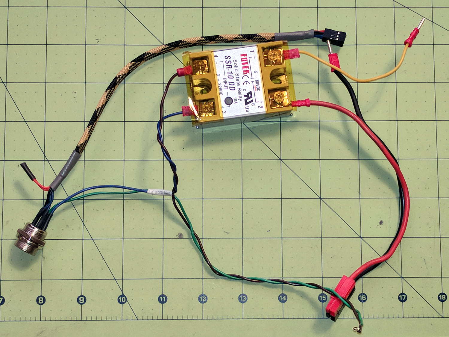
The wiring hairball between the control button pendant and the Protoneer board looks like this:
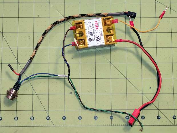
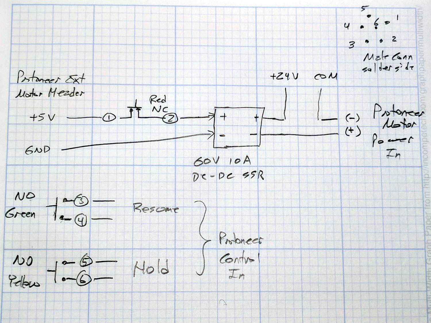
GRBL – Control button wiring The as-built schematic, such as it is:
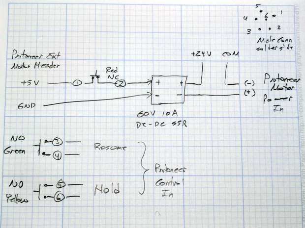
GRBL Control button wiring – sketch Yes, the SSR negative output goes to the Protoneer + Power Input.
I should drive the SSR from the
Motor Enableoutput (in the external motor control header), rather than +5 V, to let GRBL control the motors, with a manual E-Stop override. The A4988 drivers require-Enable, so:-Enableto SSR-Controlinput (replaces GND)- +5 V to BRS to SSR
+Controlinput (as before)
The SSR Control input draws 13 mA at 5 V, suggesting I should drive the AC SSR (for the spindle motor) from the DC SSR output, rather than paralleling the two on a single Arduino output pin.
I belatedly recognized the E-Stop BRS as an instantiation of an SCP-001-J Keter-class anomaly; it is now appropriately labeled:
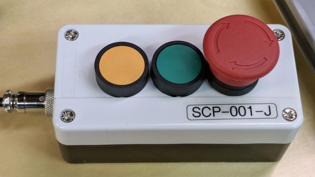
MPCNC EStop as SCP-001-J I can attest to its effect on rational thought; a molly-guard may be required.

-
Subscribe
Subscribed
Have a WordPress.com account? Log in now.

