-
Astable Multivibrator: NP-BX1 Base
Adapting the NP-BX1 battery holder to use SMT pogo pins worked well:
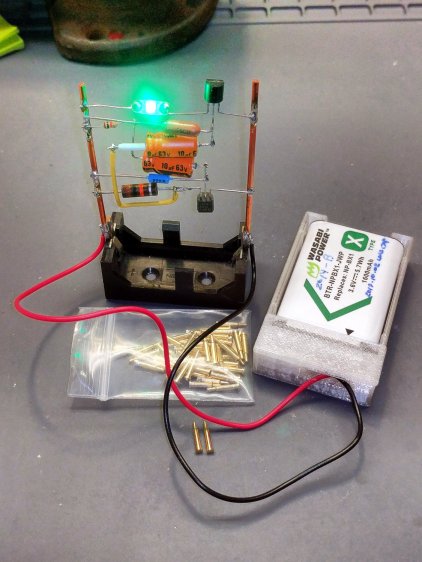
NP-BX1 Holder – SMT pogo pins The next step is to add sockets for those 14 AWG wires:

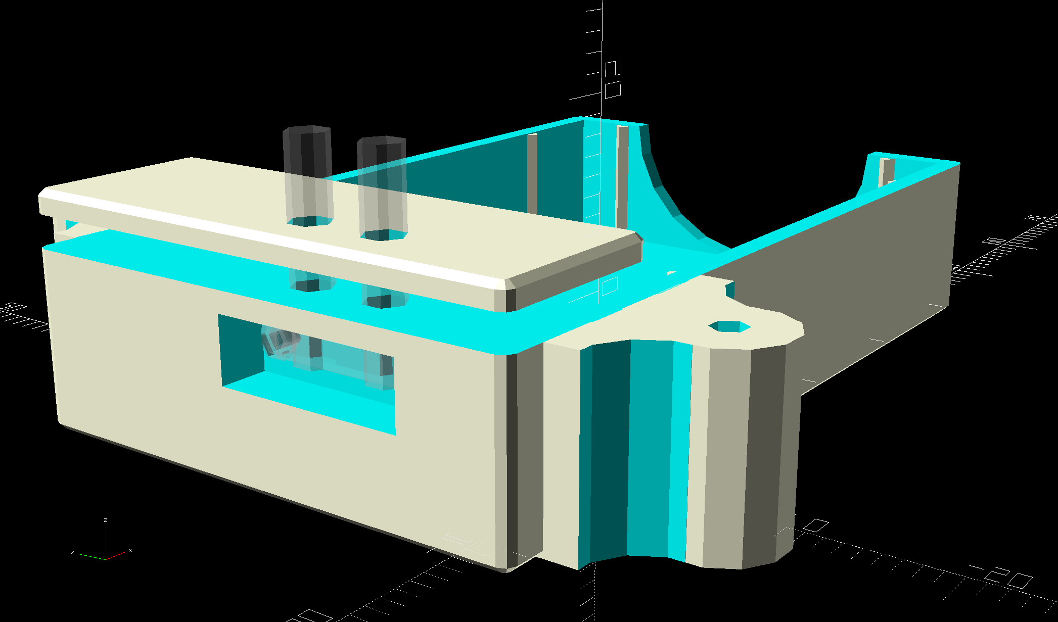
NP-BX1 Battery Holder – Wire Posts – solid model Start by reaming / hand-drilling all the holes to their nominal size and cleaning out the pogo pin pocket.
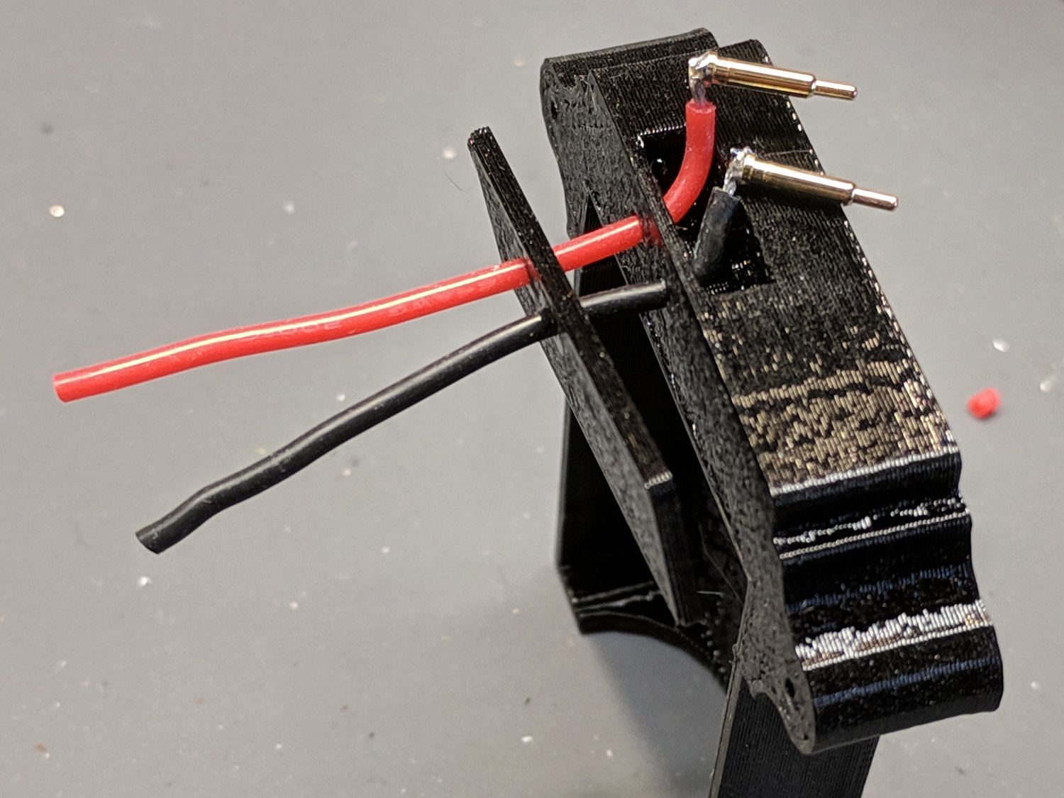
Solder wires to the pogo pins and thread them through the holder and lid:

Astable – NP-BX1 holder – pogo pin soldering That’s nice, floppy silicone-insulated 24 AWG wire, which may be a bit too thick for this purpose.
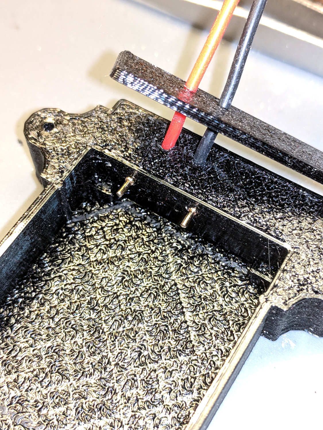
The pogo pins will, ideally, seat with the end of the body flush at the holder wall. Make it so:

Astable – NP-BX1 holder – pogo pin protrusion Dress the wires neatly into their pocket:

Astable – NP-BX1 holder – pogo pin wiring Butter the bottom of the lid with epoxy, clamp in place, set it up for curing, then fill the recess:
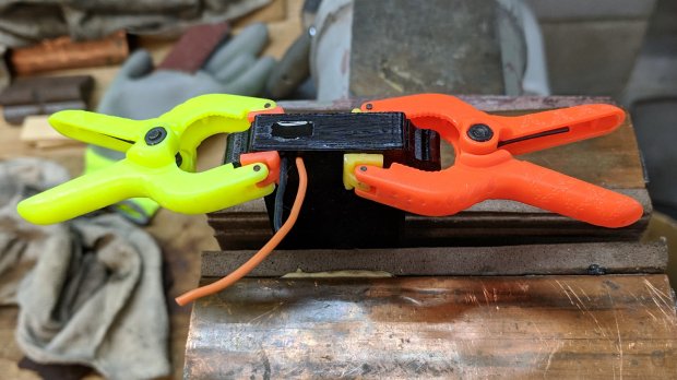
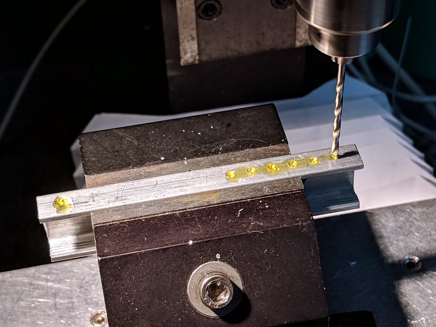
Astable – NP-BX1 base – curing While it’s curing, make a soldering fixture for the 14 AWG wires:

Astable – drilling strut soldering fixture The holes are on 5 mm centers, in the expectation other battery holders will need different spacing.
Solder it up and stick the wires into the base:
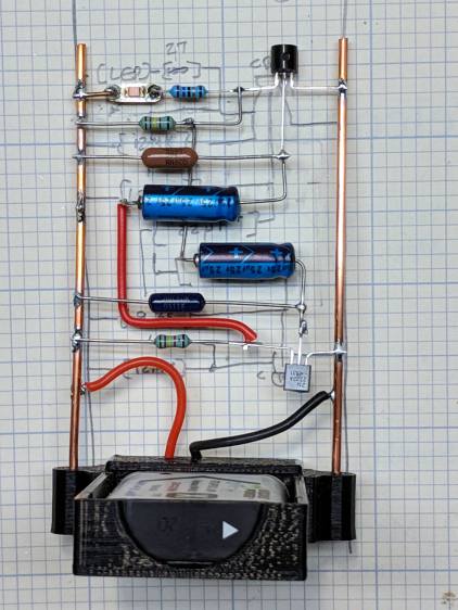
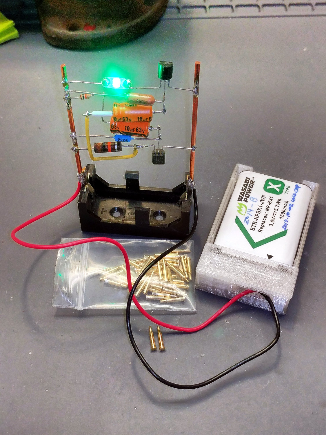
Astable – NP-BX1 base – detail Jam a battery in and It Just Works™:
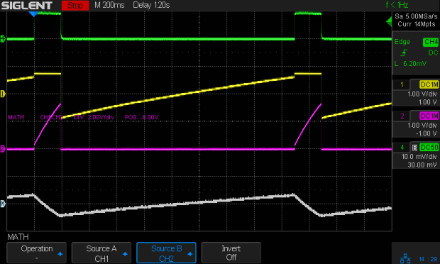
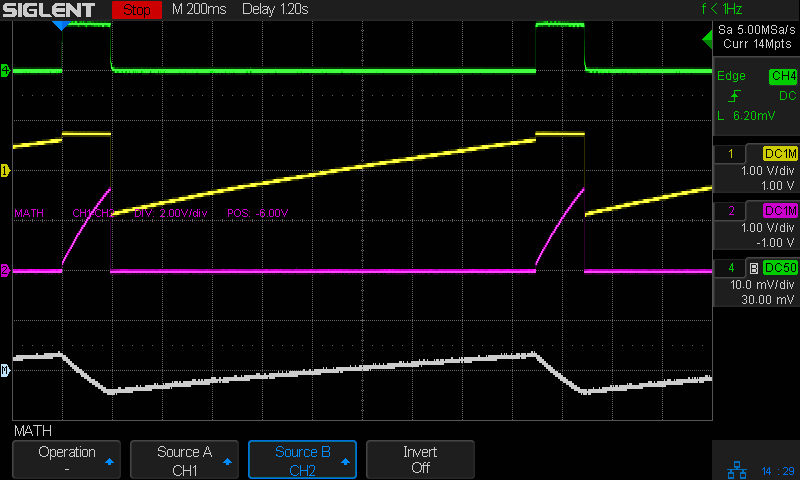
Astable – NP-BX1 3.8V – 20ma-div – cap V The traces:
- Green = supply current at 20 mA/div
- Yellow = LED driver transistor base voltage
- Purple = other transistor collector voltage
- White = base – collector voltage = capacitor voltage
The measurement setup was a bit of a hairball:
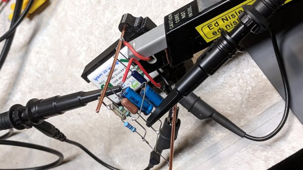
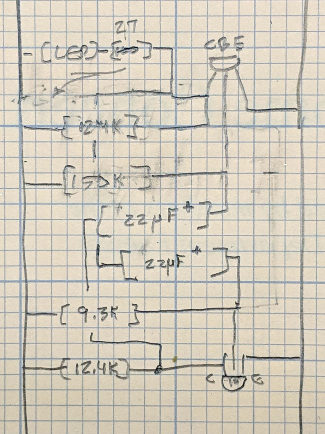
Astable – NP-BX1 base – current probe For completeness, here’s the schematic-and-layout diagram behind the circuitry:
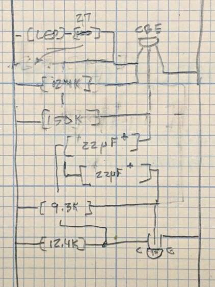
Astable – NP-BX1 base – schematic I love it when a plan comes together!
The OpenSCAD source code as a GitHub Gist:
This file contains hidden or bidirectional Unicode text that may be interpreted or compiled differently than what appears below. To review, open the file in an editor that reveals hidden Unicode characters. Learn more about bidirectional Unicode characters// Holder for Sony NP-BX1 Li-Ion battery // Ed Nisley KE4ZNU January 2013 // 2018-11-15 Adapted for wire leads from 1.5 mm test pins, added upright wire bases // Layout options Layout = "Fit"; // Show Build Fit Case Lid Pins //- Extrusion parameters – must match reality! // Print with +2 shells and 3 solid layers ThreadThick = 0.25; ThreadWidth = 0.35; HoleWindage = 0.2; function IntegerMultiple(Size,Unit) = Unit * ceil(Size / Unit); Protrusion = 0.1; // make holes end cleanly inch = 25.4; BuildOffset = 3.0; // clearance for build layout Gap = 2.0; // separation for Fit parts //- Basic dimensions WallThick = 4*ThreadWidth; // holder sidewalls BaseThick = 6*ThreadThick; // bottom of holder to bottom of battery TopThick = 6*ThreadThick; // top of battery to top of holder //- Battery dimensions – rationalized from several samples // Coordinate origin at battery contact face with key openings below contacts Battery = [43.0,30.0,9.5]; // X = length, Y = width, Z = thickness Contacts = [[-0.75,6.0,6.2],[-0.75,16.0,6.2]]; // relative to battery edge, front, and bottom ContactOC = Contacts[1].y – Contacts[0].y; ContactCenter = Contacts[0].y + ContactOC/2; KeyBlocks = [[1.75,3.70,2.90],[1.75,3.60,2.90]]; // recesses in battery face set X position //- Pin dimensions ID = 0; OD = 1; LENGTH = 2; PinShank = [1.5,2.0,6.5]; // shank, flange, compressed length PinFlange = [1.5,2.0,0.5]; // flange, length included in PinShank PinTip = [0.9,0.9,2.5]; // extended spring-loaded tip PinChannel = PinFlange[LENGTH] + 0.5; // cut behind flange for solder overflow PinRecess = 3.0; // recess behind pin flange end for epoxy fill echo(str("Contact tip dia: ",PinTip[OD])); echo(str(" .. shank dia: ",PinShank[ID])); OverTravel = 0.5; // space beyond battery face at X origin //- Holder dimensions GuideRadius = ThreadWidth; // friction fit ridges GuideOffset = 7; // from compartment corners ThumbRadius = 10.0; // thumb opening at end of battery CornerRadius = 3*ThreadThick; // nice corner rounding CaseSize = [Battery.x + PinShank[LENGTH] + OverTravel + PinRecess + GuideRadius + WallThick, Battery.y + 2*WallThick + 2*GuideRadius, Battery.z + BaseThick + TopThick]; CaseOffset = [-(PinShank[LENGTH] + OverTravel + PinRecess),-(WallThick + GuideRadius),0]; // position around battery LidOverhang = 2.0; // over top of battery for retention LidSize = [-CaseOffset.x + LidOverhang,CaseSize.y,TopThick]; LidOffset = [0.0,CaseOffset.y,0]; //- Wire struts StrutDia = 1.6; // AWG 14 = 1.6 mm StrutOC = 45; StrutSides = 3*4; StrutBase = [StrutDia,StrutDia + 4*WallThick,CaseSize.z – TopThick]; // ID = wire, OD=buildable //———————- // Useful routines module PolyCyl(Dia,Height,ForceSides=0) { // based on nophead's polyholes Sides = (ForceSides != 0) ? ForceSides : (ceil(Dia) + 2); FixDia = Dia / cos(180/Sides); cylinder(r=(FixDia + HoleWindage)/2,h=Height,$fn=Sides); } //——————- //– Guides for tighter friction fit module Guides() { translate([GuideOffset,-GuideRadius,0]) PolyCyl(2*GuideRadius,(Battery.z – Protrusion),4); translate([GuideOffset,(Battery.y + GuideRadius),0]) PolyCyl(2*GuideRadius,(Battery.z – Protrusion),4); translate([(Battery.x – GuideOffset),-GuideRadius,0]) PolyCyl(2*GuideRadius,(Battery.z – Protrusion),4); translate([(Battery.x – GuideOffset),(Battery.y + GuideRadius),0]) PolyCyl(2*GuideRadius,(Battery.z – Protrusion),4); translate([(Battery.x + GuideRadius),GuideOffset/2,0]) PolyCyl(2*GuideRadius,(Battery.z – Protrusion),4); translate([(Battery.x + GuideRadius),(Battery.y – GuideOffset/2),0]) PolyCyl(2*GuideRadius,(Battery.z – Protrusion),4); } //– Contact pins // Rotated to put them in their natural oriention // Aligned to put tip base / end of shank at Overtravel limit module PinShape() { translate([-(PinShank[LENGTH] + OverTravel),0,0]) rotate([0,90,0]) rotate(180/6) union() { PolyCyl(PinTip[OD],PinShank[LENGTH] + PinTip[LENGTH],6); PolyCyl(PinShank[ID],PinShank[LENGTH] + Protrusion,6); // slight extension for clean cuts PolyCyl(PinFlange[OD],PinFlange[LENGTH],6); } } // Position pins to put end of shank at battery face // Does not include recess access into case module PinAssembly() { union() { for (p = Contacts) translate([0,p.y,p.z]) PinShape(); translate([-(PinShank[LENGTH] + OverTravel) + PinChannel/2, // solder space ContactCenter, Contacts[0].z]) cube([PinChannel,(Contacts[1].y – Contacts[0].y),PinFlange[OD]],center=true); for (j=[-1,1]) // wire channels translate([-(PinShank[LENGTH] + OverTravel – PinChannel/2), j*ContactOC/4 + ContactCenter, Contacts[0].z – PinFlange[OD]/2]) rotate(180/6) PolyCyl(PinFlange[OD],CaseSize.z,6); } } //– Case with origin at battery corner module Case() { difference() { union() { difference() { union() { translate([(CaseSize.x/2 + CaseOffset.x), // basic case shape (CaseSize.y/2 + CaseOffset.y), (CaseSize.z/2 – BaseThick)]) hull() for (i=[-1,1], j=[-1,1], k=[-1,1]) translate([i*(CaseSize.x/2 – CornerRadius), j*(CaseSize.y/2 – CornerRadius), k*(CaseSize.z/2 – CornerRadius)]) sphere(r=CornerRadius/cos(180/8),$fn=8); // cos() fixes undersize spheres! hull() // wire strut bases for (j=[-1,1]) translate([0,j*StrutOC/2 + Battery.y/2,-BaseThick]) rotate(180/StrutSides) cylinder(d=StrutBase[OD],h=StrutBase[LENGTH],$fn=StrutSides); translate([0,Battery.y/2,StrutBase[LENGTH]/2 – BaseThick]) cube([2*StrutBase[OD],StrutOC,StrutBase[LENGTH]],center=true); } translate([-OverTravel,-GuideRadius,0]) cube([(Battery.x + GuideRadius + OverTravel), (Battery.y + 2*GuideRadius), (Battery.z + Protrusion)]); // battery space } Guides(); // improve friction fit translate([-OverTravel,-GuideRadius,0]) // battery keying blocks cube(KeyBlocks[0] + [OverTravel,GuideRadius,0],center=false); translate([-OverTravel,(Battery.y – KeyBlocks[1].y),0]) cube(KeyBlocks[1] + [OverTravel,GuideRadius,0],center=false); } translate([2*CaseOffset.x, // battery top access (CaseOffset.y – Protrusion), Battery.z]) cube([2*CaseSize.x,(CaseSize.y + 2*Protrusion),(TopThick + Protrusion)]); if (false) translate([(CaseOffset.x – Protrusion), // battery insertion allowance (CaseOffset.y – Protrusion), Battery.z]) cube([(CaseSize.x + 2*Protrusion),(CaseSize.y + 2*Protrusion),(TopThick + Protrusion)]); for (j=[-1,1]) // strut wires translate([0,j*StrutOC/2 + Battery.y/2,-(BaseThick + Protrusion)]) PolyCyl(StrutBase[ID],StrutBase[LENGTH] + 2*Protrusion,6); for (i=[-1,1], j=[-1,1]) translate([i*StrutBase[OD],j*StrutOC/2 + Battery.y/2,-(BaseThick + Protrusion)]) rotate(180/StrutSides) PolyCyl(StrutBase[OD],StrutBase[LENGTH] + 2*Protrusion,StrutSides); translate([(Battery.x – Protrusion), // remove thumb notch (CaseSize.y/2 + CaseOffset.y), (ThumbRadius)]) rotate([90,0,0]) rotate([0,90,0]) cylinder(r=ThumbRadius, h=(WallThick + GuideRadius + 2*Protrusion), $fn=22); PinAssembly(); translate([CaseOffset.x + PinRecess + Protrusion,(Contacts[1].y + Contacts[0].y)/2,Contacts[0].z]) translate([-PinRecess,0,0]) cube([2*PinRecess, (Contacts[1].y – Contacts[0].y + PinFlange[OD]), 2*PinFlange[OD]],center=true); } } // Lid position offset to match case module Lid() { difference() { translate([-LidSize.x/2 + LidOffset.x + LidOverhang,LidSize.y/2 + LidOffset.y,0]) difference() { hull() for (i=[-1,1], j=[-1,1], k=[-1,1]) translate([i*(LidSize.x/2 – CornerRadius), j*(LidSize.y/2 – CornerRadius), k*(LidSize.z – CornerRadius)]) // double thickness for flat bottom sphere(r=CornerRadius,$fn=8); translate([0,0,-LidSize.z/2]) // remove bottom cube([(LidSize.x + 2*Protrusion),(LidSize.y + 2*Protrusion),LidSize.z],center=true); translate([LidSize.x/8,0,0]) cube([LidSize.x/4,0.75*LidSize.y,4*ThreadThick],center=true); // epoxy recess } translate([0,0,-(Contacts[0].z + PinFlange[OD])]) // punch wire holes PinAssembly(); } } //——————- // Build it! if (Layout == "Case") Case(); if (Layout == "Lid") Lid(); if (Layout == "Pins") { color("Silver",0.5) PinShape(); PinAssembly(); } if (Layout == "Show") { // reveal pin assembly difference() { Case(); translate([(CaseOffset.x – Protrusion), Contacts[1].y, Contacts[1].z]) cube([(-CaseOffset.x + Protrusion), CaseSize.y, (CaseSize.z – Contacts[0].z + Protrusion)]); translate([(CaseOffset.x – Protrusion), (CaseOffset.y – Protrusion), 0]) cube([(-CaseOffset.x + Protrusion), Contacts[0].y + Protrusion – CaseOffset.y, CaseSize.z]); } translate([0,0,Battery.z + Gap]) Lid(); color("Silver",0.15) PinAssembly(); } if (Layout == "Build") { translate([-(CaseSize.x/2 + CaseOffset.x),-(CaseOffset.y – BuildOffset),BaseThick]) Case(); translate([CaseSize.x/2,-LidSize.x/2,0]) rotate(90) Lid(); } if (Layout == "Fit") { Case(); translate([0,0,(Battery.z + Gap)]) Lid(); color("Silver",0.25) PinAssembly(); }




-
Subscribe
Subscribed
Have a WordPress.com account? Log in now.

